installation &
operating instructions
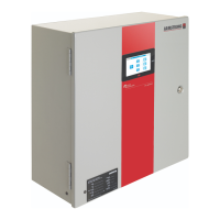
ips 4000 controller - Integrated pumping
system for variable primary applications
5
2.0 ips 4000 function displays
The ips 4001 / 4002 / 4003 controllers displays are divided
in two set of displays: Operation and Setup. The Operation dis-
plays are used by the operators to monitor and control the ips.
The Setup screens are used to set, view, save, and restore the
system specific settings (i.e. number of pumps, chillers/boilers,
sensor range, etc.).
operation displays:
• Main menu
• System overview
• Zone overview
• Pump overview
• Sensorless overview
• Pump control
• Bypass valve overview
• Auto bypass reset
• Login
• Alarm overview
• Diagnostics
setup displays:
The setup displays are divided in three levels each with dier-
ent level of access. Level 0 setup displays are for viewing only
and no adjustments can be made. Level 1 setup displays can be
used for changing the system setup and restoring the system
factory defaults. Level 2 setup displays can be used for chang-
ing the system setup, and saving and restoring the system
factory defaults. To access Level 1 and 2 an operator need to
enter the proper password (please contact Armstrong factory
service department).
The list of setup/default displays for every level is as follow:
• System setup
• Zone setup
• Zone 1 to 12 setup
• Sensorless setup
• Pump setup
• Speed setup
• Staging setup
• pid setup
• bas setup
• Clock setup
• Bypass valve setup
• System valves setup
• vfd readout setup
• Chiller/boiler 1 to 6 setup
• Flow setup