installation &
operating instructions
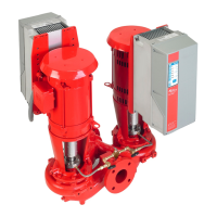
Design Envelope 4312 and 4392 vertical in-line
twin pumping unit with ivs drive
7
1 m (40") clearance in front of
controls may be required in
your locale
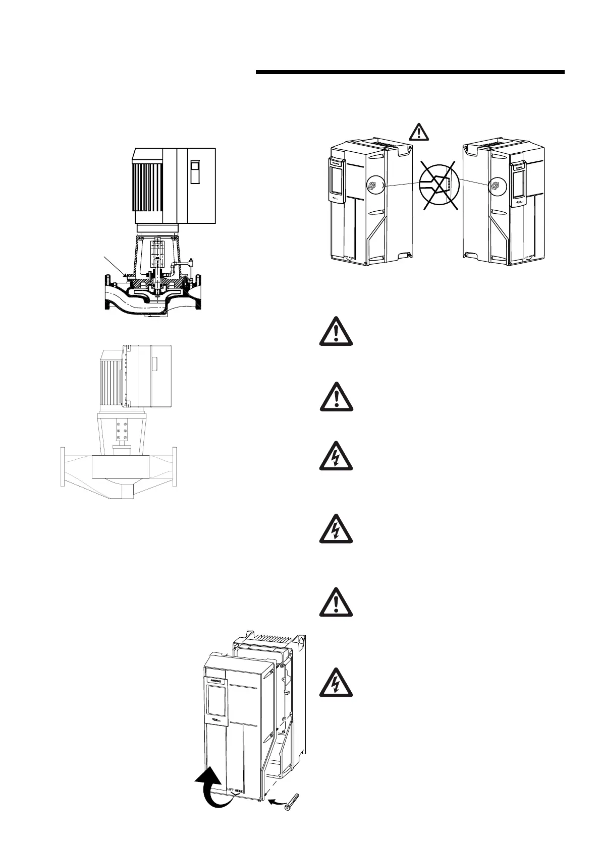
fig. 1.8 tapped collection well on design
envelope 4312
4312
seal leaks or condensate
dr
ain hole. Plumb to
ain for area
s
fig. 1.9 clearance note
2.0 electrical setup
2.1 remove cover
Remove front cover to access mains and grounding connec-
tions, and control terminals. Carefully lift the cover from the
bottom edge to remove. do not pry the cover open from
the side edges.
When replacing the front cover,
please ensure proper fastening
by applying a torque of 2Nm.
do
not
pry
do
not
pry
do not
pry
from
sides
2.2 precautions
The standard enclosure rating for Design Envelope
4302 and 4382 integrated controls is nema/ul type
12. If the pump is to be installed in a wet or dusty
environment then a higher enclosure rating may be
required (contact Armstrong)
To avoid the inverter unit getting overheated, the
ambient temperature is not to exceed 133°f (45°c).
Operating in higher ambient temperatures will
require derating of the inverter.
All electrical connections should be carried out by a
qualified and authorized electrician in accordance
with local site regulations and the latest issue of the
iee regulations.
safety, risk of death
Before removing the controls cover, the system
must be disconnected from the mains supply. After
switching o, wait for at least 15 minutes for the
capacitors to discharge before opening the cover.
caution
High voltage testing (Megging) of the motor/ con-
trols may cause damage to the electronic compo-
nents and therefore should not be carried out.
2.2.1 ground leakage current
Ground leakage current is primarily caused by the
capacitance between motor phases and the motor
frame. The rfi filter contributes additional leakage
current, as the filter circuit is connected to ground
through capacitors.
The size of the leakage current to the ground depends on the
following factors, in order of priority:
1 Switching frequency
2 Motor grounded on site or not
The leakage current is of importance to safety during han-
dling / operation of the Design Envelope pump if (by mis-
take) the on-board inverter has not been grounded.


 To Next Page