installation &
operating instructions
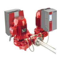
Design Envelope 4312 and 4392 vertical in-line
twin pumping unit with ivs drive
9
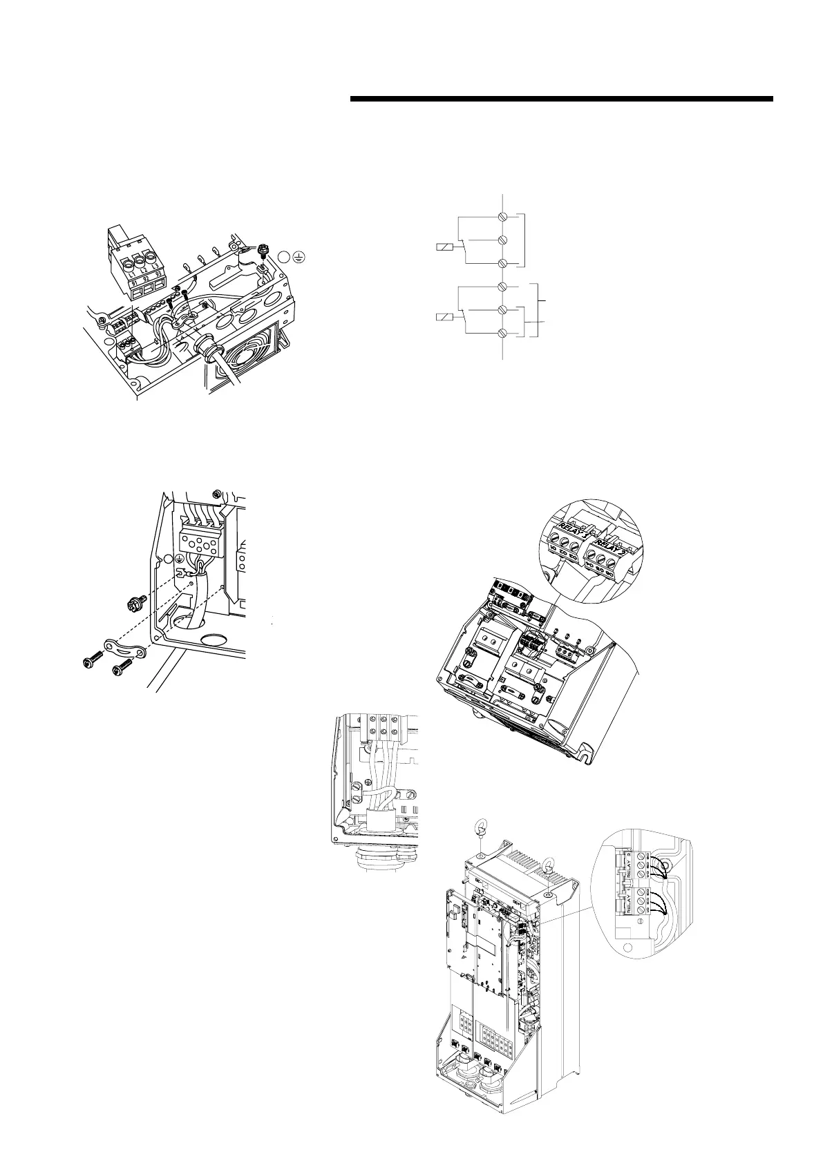
fig. 2.2 Mains and grounding connections for a5 units
(200-240V - 1.5hp 1ph/5hp and below 3ph,
380-480V/525-600V - 10hp and below)
fig. 2.3a Mains and grounding connections for b1 and
b2 units (200-240V - 2 to 7.5hp 1ph / 7.5 to
20hp 3ph, 380-480V - 15 to 40hp, 525-
600V – 15 to 50hp)
fig. 2.3b Mains and grounding con-
nections for c1 and c2 units
(200-240V – 25 to 60hp,
380-480V – 50 to 125hp,
525-600V – 60 to 125hp)
2.3.4 relay connections
The relays on the ivs are configured as follows:
Relay 1 – alarm
• Terminal 01: Common
• Terminal 02: Normal Open 240v ac
• Terminal 03: Normal Closed 240v ac
Relay 2 – run status
• Terminal 04: Common
• Terminal 05: Normal Open 400v ac
• Terminal 06: Normal Closed 240v ac
fig. 2.4 relay contact details
04
05
06
01
02
03
240v ac, 2a
Relay 1
Relay 2
The following illustrations identify the location of the relays
within specific inverter sizes:
The illustrations in figures 6, 7 and 8 identify the location of
the relays within specific inverter sizes:
fig. 2.5 relay connection: terminals for a5, b1
and b2 units
fig. 2.6 relay connection terminals for c1
and c2 units
95
95
91
L1
92
L2
93
L3


 To Next Page