installation &
operating instructions
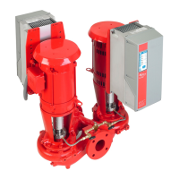
Design Envelope 4312 and 4392 vertical in-line
twin pumping unit with ivs drive
8
Since the leakage current is >3.5ma (approx
4-20ma), reinforced Grounding must be established
which is required if en 50178 is to be complied with.
Never use elcb relays that are not suitable for dc
fault currents (type a).
If elcb relays are used, they must be:
•
Suitable for protecting equipment with a direct current con-
tent (dc) in the fault current (three-phase bridge rectifier)
• Suitable for power-up with short charging current to
Ground
• Suitable for a high leakage current
2.2.2 start / stop of pump
The number of starts/stops via the mains voltage must not
exceed one-time per minute.
If a higher number of starts/stops is required then the start/
stop digital input must be used (mains voltage directly con-
nected). This is the preferred method of starting and stop-
ping Design Envelope pumps.
The three phase mains must be isolated before performing
maintenance of the pump.
2.2.3 additional motor protection
With the exception of supply fuses / mcb’s to
protect the installation (for over-current and
short-circuit protection), no additional overload or
over-temperature protection is required (i.e. thermal
overloads). Protection features include:
• Mains phase loss
• Over voltage
• Under voltage
• Electronic thermal motor protection
• Short circuit on motor terminals
• Ground fault on motor terminals
• Over temperature
2.3 electrical installation
2.3.1 supply voltage
The supply voltage details can be found on the ivs102 name-
plate. Please ensure that the unit is suitable for the electrical
supply on which it is to be used. The mains supply for Design
Envelope pumps is as follows:
1 × 200-240v ± 10%
3 × 200-240v ± 10%
3 × 380-480v ± 10%
3 × 525-600v ± 10%
Supply frequency - 50/60Hz
2.3.2 supply fusing
Branch circuit protection
In order to protect the installation against electrical and fire
hazard, all branch circuits in an installation, switch gear, ma-
chines etc., must be short-circuit and over-current protected
according to the national/international regulations.
Short circuit protection
The inverter must be protected against short-circuit to avoid
electrical or fire hazard. Armstrong recommends using the
fuses detailed in the separate ivs Operating Instructions to
protect service personnel or other equipment in case of an
internal failure in the unit. The frequency converter provides
full short circuit protection in case of a short-circuit on the
motor output.
2.3.3 grounding and it mains
The ground connection cable cross section must
be at least 10 mm
2
or two rated mains wires
terminated separately according to en 50178 or
iec 61800-5-1 unless national regulations specify dier-
ently. Always comply with national and local regulations on
cable cross sections.
The mains is connected to the main disconnect
switch if this has been included.
Check the mains voltage corresponds to the mains
voltage of the frequency converter name plate.
Do not connect frequency converters with rfi-fil-
ters to mains supplies with a voltage between
phase and earth of more than 440v for 400v
converters and 760v for 690v converters. For 440v it mains
and delta earth (grounded leg), mains voltage may exceed
440v between phase and earth. For 690v it mains and delta
earth (grounded leg), mains voltage may exceed 760v
between phase and earth.
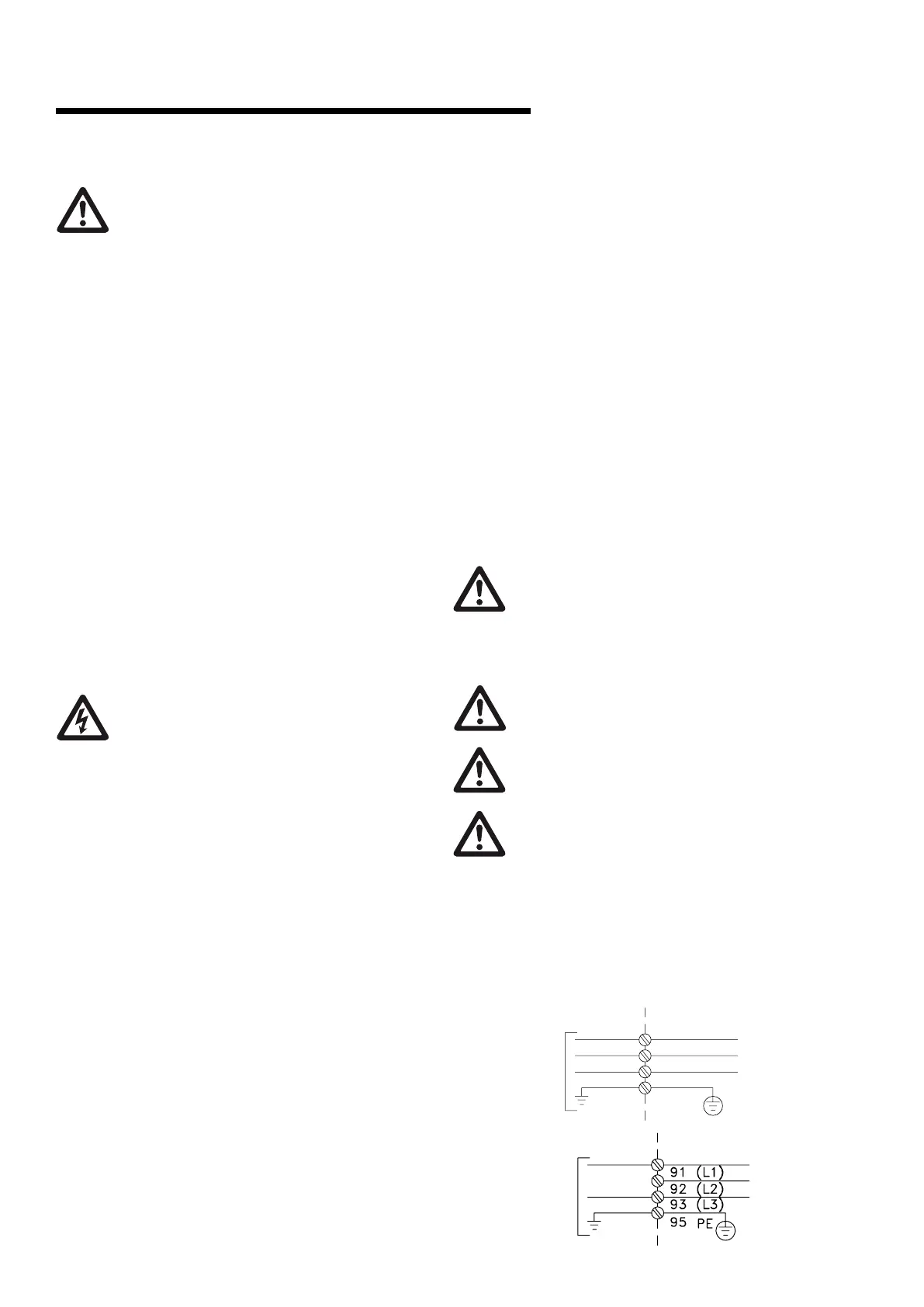
fig. 2.1 terminals for mains and grounding
3 phase
power input
2. Place plug connector 91, 92, 93 from the accessory bag onto the terminals labelled MAINS at the bottom of the frequency converter.
3. Connect mains wires to the mains plug connector.
The earth connection cable cross section must be at least 10 mm
2
or 2 rated mains wires terminated separately according to EN 50178.
The mains connection is fitted to the main switch if this is included.
NB!
Check that mains voltage corresponds to the mains voltage of the frequency converter name plate.
IT Mains
Do not connect 400 V frequency
converters with RFI-filters to mains supplies with a voltage between phase and earth of more than
440 V.
For IT mains and delta earth (grounded leg), mains voltage may exceed 440 V between phase and earth.
Illustration : Terminals for mains and earthing.
5 How to Install VLT
®
AQUA Drive Design Guide
122
MG.20.N5.02 - VLT
®
is a registered Danfoss trademark
5
1 phase
power input


 To Next Page