Antenna Analyzer AIM4170 page 25
The following pictures show the effect of using the impedance transformation feature.
These graph illustrate the results using reference Method A.
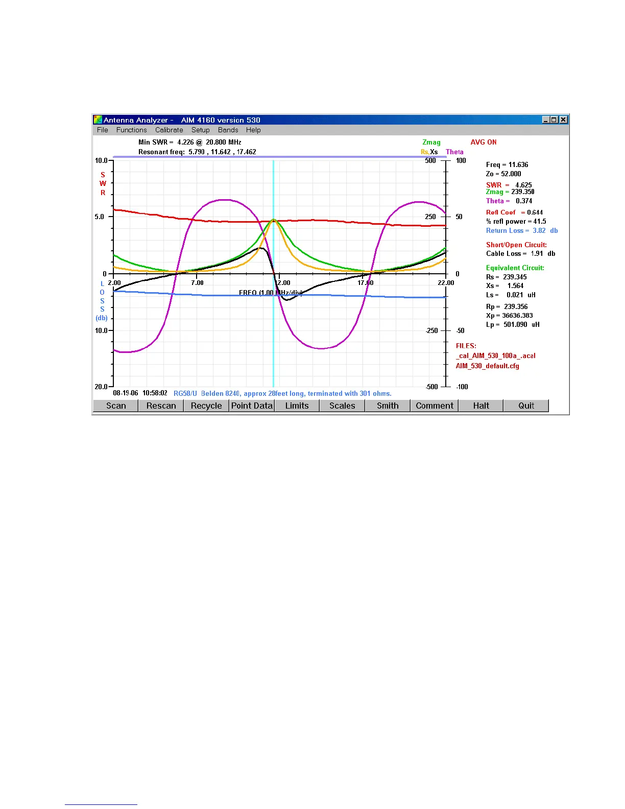
This picture shows an ordinary scan with a 301-ohm resistor at the end of 28 feet of
RG58 coax. The Green trace is the magnitude of the measured impedance. As expected,
this is a complex function of frequency. The magnitude of the impedance at the half-
wavelength frequency is only 239 ohms instead of the expected 301 ohms because of loss
in the cable.
Now we click Functions on the top menu line and Refer to Antenna. The legend “Ref to
Antenna” is displayed in Red at the top of the graph when this feature is enabled.