Antenna Analyzer AIM4170 page 26
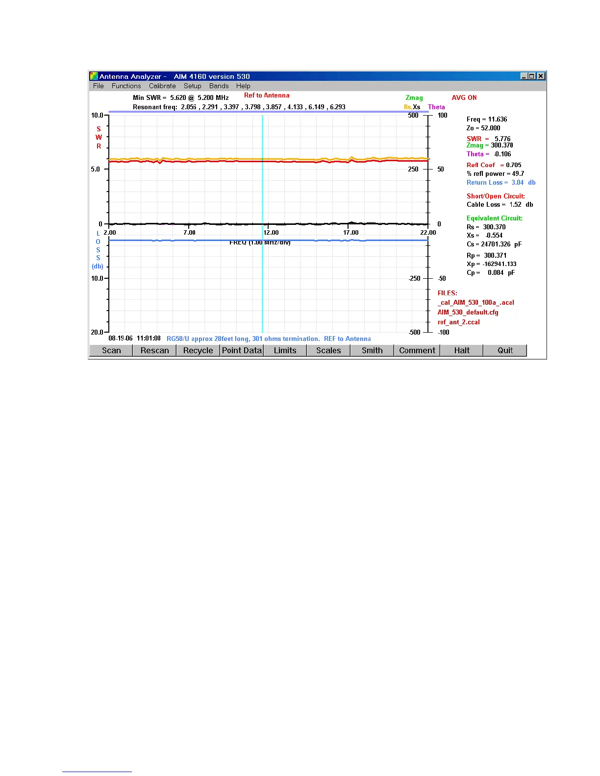
This picture shows the results when the Refer to antenna function is selected. The
resistor (301 ohms) and the cable are the same as used in the previous graph. The Rs plot
(shown in orange) is relatively flat across the frequency range. (The magnitude of the
impedance is plotted in green but it is overlaid by the orange plot since the values of
Zmag and Rs are so close in numeric value.) The measured resistance at 11.363MHz is
300.4 ohms. It’s very close to the true value now because the cable loss has been
compensated by the calibration procedure.
The next graph shows the transformation works quite well with a complex load. A
parallel R-L-C tuned circuit was used for the load. The first plot shows a scan with the
circuit connected directly to the BNC connector. The second plot shows the same circuit
at the end of 28 feet of RG58/U after calibrating the cable and enabling the Refer to
Antenna mode.