III
IMPORTANT SAFETY INSTRUCTIONS – READ FIRST ......................................................... II
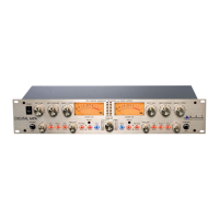
DIGITAL MPA II OVERVIEW – FEATURES AND GENERAL INFORMATION: ...................... 1
FRONT PANEL CONNECTIONS AND CONTROLS ................................................................ 3
Input Gain control ..................................................................................................................................... 3
Input Impedance control ...........................................................................................................................4
Low Cut Filter control................................................................................................................................4
Gain switch ............................................................................................................................................... 4
Phantom switch ........................................................................................................................................5
Phase switch............................................................................................................................................. 5
Plate Voltage switch ................................................................................................................................. 5
Mid/Side switch.........................................................................................................................................6
Analog Output control ...............................................................................................................................6
STEREO/Dual switch................................................................................................................................ 6
+4/-10 switch (rear panel).........................................................................................................................7
Meter Trim ................................................................................................................................................ 7
Digital section front panel controls........................................................................................ 7
Digital Level control .................................................................................................................................. 7
Sample Rate control .................................................................................................................................8
Dither settings........................................................................................................................................... 9
Optical switch............................................................................................................................................9
Front Panel connections ....................................................................................................... 10
Instrument Inputs .................................................................................................................................... 10
Rear Panel connections ........................................................................................................ 11
Balanced Inputs ...................................................................................................................................... 11
Balanced Outputs ...................................................................................................................................11
Insert jacks.............................................................................................................................................. 12
Wordclock jacks...................................................................................................................................... 12
ADAT Input ............................................................................................................................................. 12
Optical output.......................................................................................................................................... 12
S/PDIF output .........................................................................................................................................13
AES/EBU output .....................................................................................................................................13
DIGITAL MPA II OPERATING INSTRUCTIONS..................................................................... 14
Obtaining the best noise performance with the DIGITAL MPA II............................................................ 14
Adjusting the Input Impedance ...............................................................................................................14
Obtaining the perfect digital level setting ................................................................................................ 15
Setting the Tube Plate Voltage ...............................................................................................................16
Using the Mid/Side mode........................................................................................................................ 17
WARRANTY INFORMATION.................................................................................................. 18
SERVICE ................................................................................................................................. 19
DIGITAL MPA II SPECIFICATIONS........................................................................................ 20
Analog Section:....................................................................................................................................... 20
Digital Section:........................................................................................................................................ 20
List of Figures
Figure 1 – Block Diagram .......................................................................................................... 2
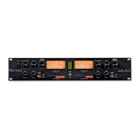
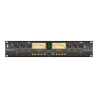
Figure 2 – Front controls............................................................................................................ 3
Figure 4 – Rear connections .................................................................................................... 11
Figure 4 – Mid/Side Mic alignment........................................................................................... 17
 Loading...