6
High Voltage Instrument Transformers | CA/UT/KA
User Manual - Annex III
The Portable Transformer Ratio Meter (TTR) is commonly used
to measure the ratio, excitation current and polarity of windings.
The values obtained are a reference that the transformer is
in good condition and can be energized. They should not be
compared with the results of factory tests carried out in the
manufacturing plant laboratory.
Due to the high precision required for this measurement, the
actual uncertainty of the test must be taken into account when
testing on site.
The TTR contains 4 terminals (this confi guration may vary
depending on the manufacturer):
› H1: Black excitation terminal.
› H2: Red excitation terminal.
› X1: Black secondary terminal.
› X2: Secondary red terminal.
TRANSFORMER RATIO TEST
To carry out the test, it will be necessary to excite the transformer
on the secondary side if a TTR is used, because this is where the
highest number of turns are located.
This test verifi es the transformer ratio and polarity, and displays
a “+” signal if correct, and a “-” signal if inverted. To carry out the
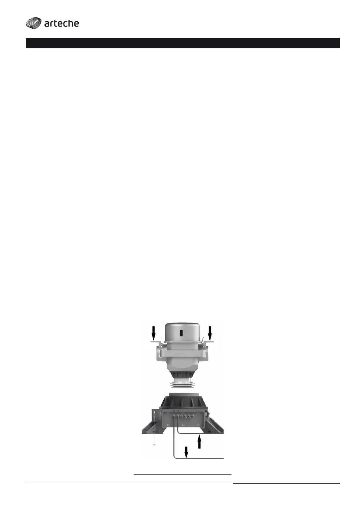
test, proceed as follows (Fig. 10).
› The clamps marked “X” will be connected to the transformer’s
primary terminals:
• X1 will be connected to the CT’s main terminal.
• X2 will be connected to the other primary terminal.
› The excitation terminals (the clamps marked “H”) will be
connected to the transformer’s secondary terminals:
• H1 will be connected to the positive polarity terminal of the TI.
• H2 will be connected to the negative polarity terminal of the TI.
• The remaining secondaries must be short circuited.
CURRENT TRANSFORMERS/
› Fig. 10
X2
P2
X1
P1
H1
H2