7
High Voltage Instrument Transformers | CA/UT/KA
User Manual - Annex III
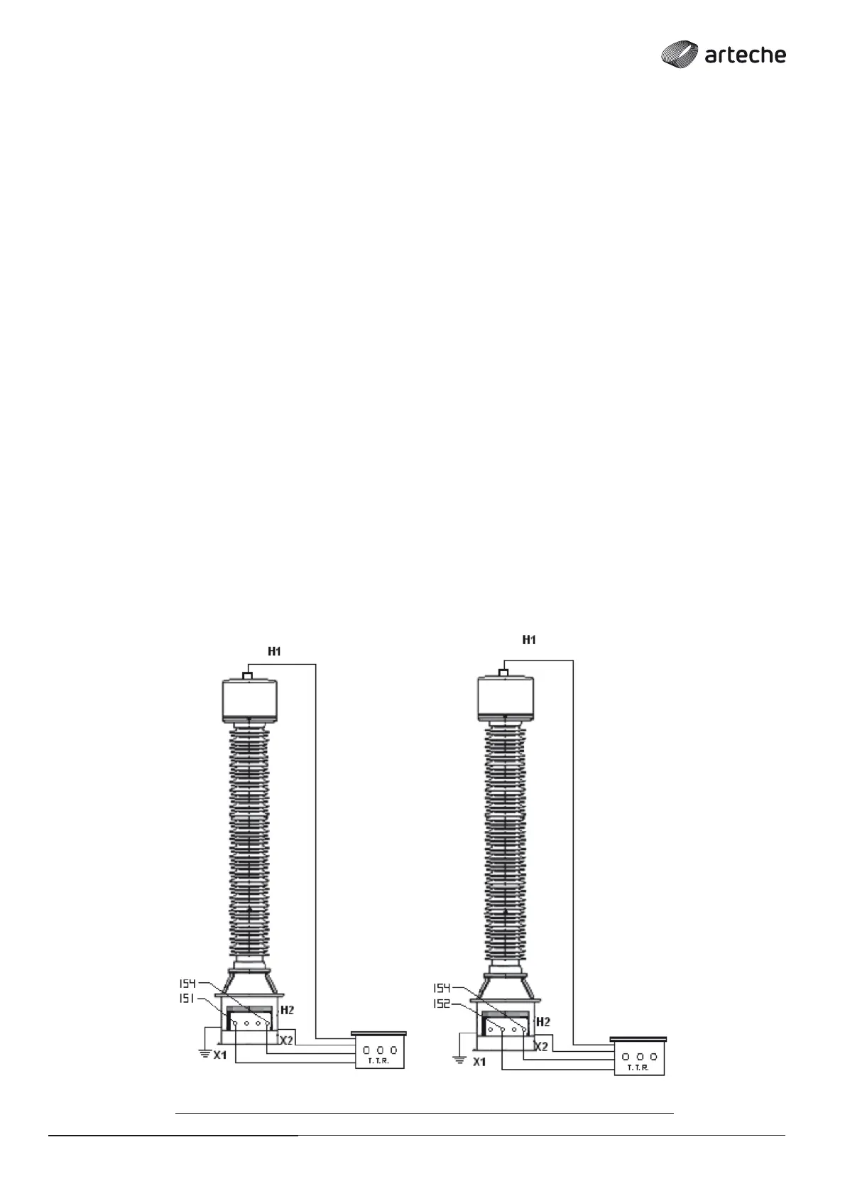
This test verifi es the transformer ratio and polarity, and displays
a “+” signal if correct, and a “-” signal if inverted. To carry out the
test, proceed as follows (Fig. 11).
› The excitation terminals (clamps marked “H”) will be
connected to the transformer’s primary terminal:
• H1 will be connected to the primary terminal of equipment A.
• H2 will be connected to the ground terminal, located at the
base of the equipment.
› The clamps marked “X” will be connected to the transformer’s
secondary terminals:
• X1 will be connected to 1S1. When the secondary has taps, you
must connect X1 to the tap of the secondary terminal which
is to be tested.
• X2 will be connected at the end of the secondary terminal.
• This test must be applied to each secondary separately;
in case the transformer has more than 1 secondary, the
secondary(s) which are not to be tested must be left open.
INDUCTIVE VOLTAGE TRANSFORMERS/
› Fig. 11
A A
 Loading...