EasyManua.ls Logo

ARTEX 453-6611 - User Manual

ARTEX 453-6611
74 pages
Print Icon
To Next Page IconTo Next Page
Loading...
Page 1 of 74
MAY 28/2020
570-1700 Rev. V
Initial Issue JAN 05/2007
ARTEX PRODUCTS / ACR ELECTRONICS, INC.
5757 Ravenswood Rd, Ft. Lauderdale, FL 33312
Cage Code: 18560
25-62-31
ME406 Series
Emergency Locator Transmitter
Description, Operation, Installation and Maintenance Manual
This manual includes data for the equipment that follows:
Component Part No. Model No.
Emergency Locator Transmitter 453-6611 ME406P

Table of Contents

Questions and Answers

  • K
    Kayla MooreAug 9, 2025
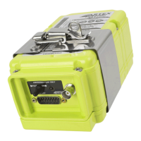
    What to do if my ARTEX Transmitter shows a 4-Flash?
    • H
      hunter13Aug 9, 2025
      A 4-Flash indicates that the 406 or 121.5 MHz output power is low, or the transmitter module is faulty. First, check the coax cable and connections, and ensure the antenna is properly installed. If the issue persists, and the transmitter module frequency is out of limits, it cannot be repaired in the field and should be returned to the factory for servicing. You may also try lengthening or shortening antenna coax cable length by 4 to 6 inches.
  • M
    Melinda TorresAug 28, 2025
    Why does my ARTEX Transmitter show 5-Flash?
    • J
      John ZimmermanAug 29, 2025
      A 5-Flash indicates there is no navigation position data present (long message protocol only). You can reprogram to short message or ignore the error code. The 5 flash code does not indicate a hard failure and does not affect the airworthiness of the unit.
  • E
    Eduardo HowellNov 19, 2025
    How to fix ARTEX Transmitter when it shows 3-Flash?
    • M
      Michael KempNov 19, 2025
      A 3-Flash indicates a 406 MHz transmission problem. Verify the coax cable/antenna is connected and in good condition and perform a continuity check of the center conductor and shield, checking for a shorted cable. Also, use a VSWR meter to check the antenna for opens, shorts, or a resistive ground plane connection. Try lengthening or shortening the antenna coax cable length by 4 to 6 inches, and provide a ground plane at least 12 inches in diameter. Ensure you stay at least 10-12 inches away from upright metal structures. Check if the battery is low or if the 3A fuse on the battery pack circuit board is faulty. Verify continuity between antenna ground plane and ELT local ground connection. If the transmitter module is faulty, it cannot be repaired in the field and must be returned to the f...

Summary

Introduction

Model Description

Detailed description of the ME406P ELT and its features.

Description and Operation

Description

Details on the ELT's functional overview and components.

Operation

How to operate the ELT, including manual and portable modes.

Specifications

Environmental, physical, and electrical specifications of the ELT.

Test and Fault Isolation

Inspection and Test Regulatory Requirements

Requirements for ELT inspection and testing in different regions.

Inspection and Test Procedures

Step-by-step procedures for inspecting and testing the ELT.

Fault Isolation

Guidelines for troubleshooting ELT errors and symptoms.

Removal

Installation

Regulatory Requirements and Guidelines

Regulations and guidelines for ELT installation in various regions.

General Wiring Considerations

General considerations and recommendations for ELT wiring.

ELT Installation

Procedures for installing the ELT into the mounting tray.

Appendix A - ELT Registration

ARTEX 453-6611 Specifications

General IconGeneral
BrandARTEX
Model453-6611
CategoryTransmitter
LanguageEnglish

Related product manuals