Do you have a question about the ARTEX ELT 4000S and is the answer not in the manual?
Document contains proprietary information not to be disclosed without permission.
Specifies FAA-approved airworthiness limitations and maintenance requirements.
Outlines ACR Electronics' responsibility for ICA distribution and revisions.
Explains the 406 MHz beacon signal transmission via satellite.
Guides on how to use the manual and its contents.
Details the applicability of the ELT and the manual for regulatory requirements.
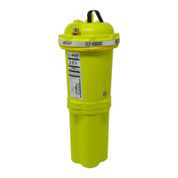
Details the ARTEX ELT 4000S as a Class 2 Survival beacon.
Lists the regulatory approvals for the ELT, including FAA, Transport Canada, etc.
Addresses the 406 - 406.1 MHz transmitter frequencies for distress bands.
Explains frequency transmission and how it's controlled by Cospas-Sarsat.
Lists and refers to relevant regulatory documents like AC, CFR, FAR, TSO.
Lists other supporting documents like programmer/tester manuals available from ACR.
Provides a general overview of how the Survival ELT activates and transmits signals.
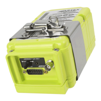
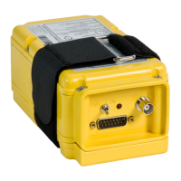
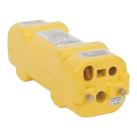
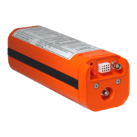
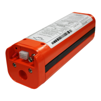
Details the physical components of the ELT 4000S, including its case and LEDs.
Describes the simplicity of operation, activation indicators, and deactivation procedures.
Explains how to deploy the antenna and set the toggle switch for normal operational readiness.
Details how to manually activate the ELT using the toggle switch.
Explains how to reset the ELT after an inadvertent activation.
Recommends periodic self-tests and discusses battery capacity for testing.
Lists environmental and physical specifications like temperature, vibration, shock, weight, and dimensions.
Details the electrical specifications including operating frequencies, modulation, and power output.
Outlines the procedures for inspecting and testing the ELT's operational status.
Steps for preparing the ELT for inspection, including removal from mount and battery.
Details inspection of the ELT bracket and hardware for cleanliness, cracks, and corrosion.
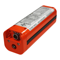
Guides on inspecting the battery pack for damage, corrosion, and checking expiration dates.
Describes visual inspection of connectors and main board for damage or corrosion.
Details the procedure for checking the functionality of the ELT's water sensor contacts.
Details setup for testing ELT performance, including battery test time and test equipment.
Details how to measure 121.5 MHz frequency and perform audio modulation check.
Explains how to measure the 121.5 MHz power output of the ELT.
Details how to measure the 406 MHz frequency after stabilization.
Explains how to measure the 406 MHz power output of the ELT.
Details the procedure for testing the current draw of the ELT in different states.
Describes how to verify the transmitted digital message using a programmer/tester.
Verifies the proper reset function of the ELT after activation.
Outlines the procedure for testing the ELT antenna by checking for 121.5 MHz presence.
Covers the process of installing the transmitter and securing it with a strap.
Details the documentation requirements for completed ELT inspections and tests.
Explains the ELT self-test function, its indications, and recommended frequency.
Describes the GNSS Self-Test mode for verifying navigation system interface operation.
Steps for preparing the battery pack for inspection or replacement.
Guides on how to remove and replace the ELT battery pack, including safety precautions.
Provides steps for installing the ELT bracket, including switch position and antenna securing.
Details the steps for removing the ELT from its bracket, including pin release and arm swing.
Information required when returning material or equipment to the factory.
Details the process for obtaining a Return Material Authorization (RMA) number.
Introduces the purpose and usage guide for the illustrated parts list.
Explains that the IPL illustrates and lists spare parts and attaching hardware for the ELT.
Provides instructions on how to use the Illustrated Parts List effectively.
Explains the Hex ID code, its programming, transmission, and labeling.
Details why ELT registration is important for rescue coordination centers.
Points to Cospas-Sarsat documents for ELT programming and registration information.
Details owner responsibilities, required info, and where to register the ELT.
| Type | Emergency Locator Transmitter (ELT) |
|---|---|
| Operating Temperature | -20°C to +55°C (-4°F to +131°F) |
| Frequency | 121.5 MHz, 406 MHz |
| Battery Life | Up to 48 hours |
| Activation | Automatic or Manual |
| Battery | Lithium |
| Standards | COSPAS-SARSAT, FAA TSO C126 |
| Activation Method | Manual switch |