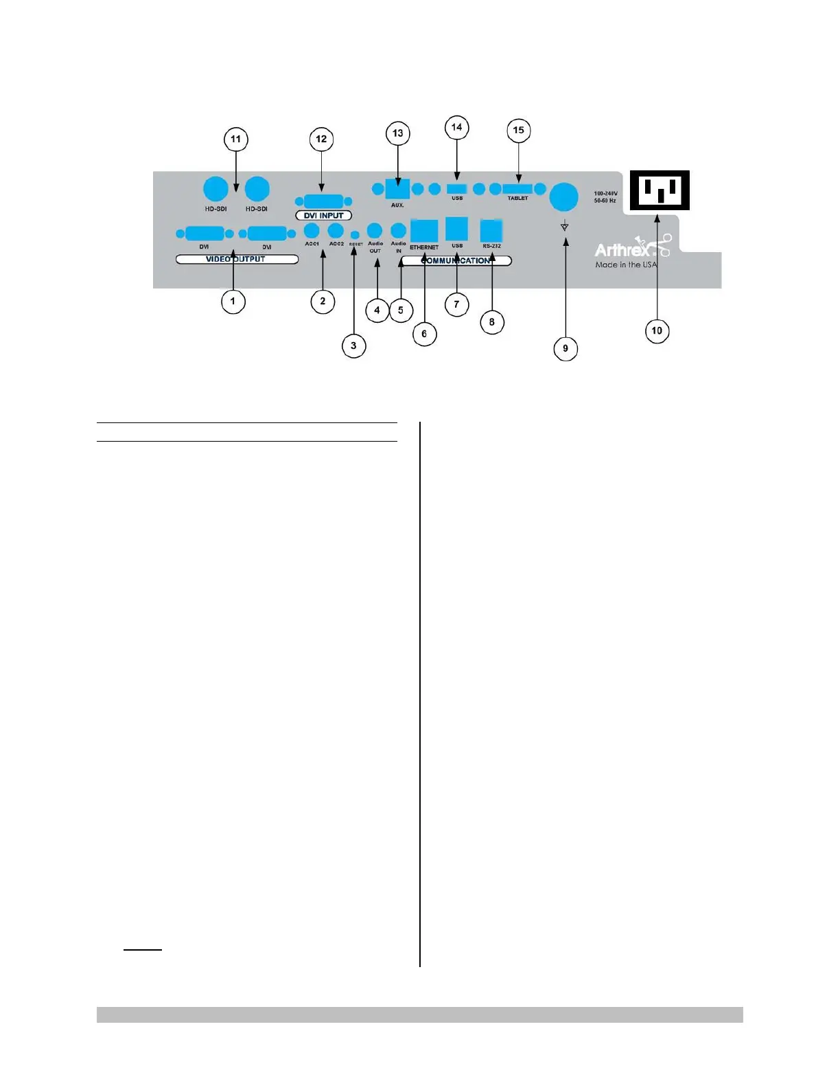
1.9.2 Rear Panel
1. “DVI” Video Output Connectors —
Supplies a digital video signal output in DVI-
D format.
2. Accessory Ports (Inputs/Outputs - 2X
mini Stereo-Phone Connectors) —
Accessory ports allow for control of the
Camera Control Unit (CCU) with a
footswitch, or for the CCU to control external
devices through the camera head buttons.
3. Reset Button — Resets CCU to factory
Defaults.
4. Audio Out- Line Level audio output to
Medical Grade devices.
5. Audio IN-Line Level audio input for
Microphone
6. Ethernet Connector- Isolated-10/100
MB/Sec.
7. USB Connector - Connect USB devices
here.
8. RS-232 Connector-Isolated-connection to
devices requiring Serial Control.
9. Potential Equalization Connector (POAG)
— Potential Equalization Connector per DIN
42801.
NOTE: The purpose of the Potential
Equalization Connector is to equalize the
potentials between different metal parts of
the various Medical Electrical [ME]
equipment which make up a Medical
Electrical system, or to reduce differences of
potential which can occur during operation
between the bodies of the Medical Electrical
devices and conductive parts of other
objects. The Potential Equalization
Connector may be connected directly
between any ME Devices, or to a common
busbar of the electrical installation.
Reference IEC 60601-1 for ME Systems.
10. IEC 320 Power Inlet Module (100-240V~,
50/60 Hz) — The CCU is equipped with a
switching power supply that automatically
adjusts to the line voltage being used.
Accepts the supplied hospital grade power
cord.
11. HDSDI- 3G Serial Video Output
12. DVI Input – 1080P/60 input from other
medical devices
13. AUX-Ethernet connection
14. USB – USB Connection
15. USB TABLET CONNECTION– Connect
Tablet Data Input device here. Provides for
data interchange and tablet charging.
 Loading...