Aruba 310 Series Access Points | Installation Guide 3
LED Display Settings
The LEDs have three operating modes that can be selected in the system management software:
Default mode: Refer to Table 1 and Table 2
Off mode: LEDs are off
Blink mode: LEDs blink green
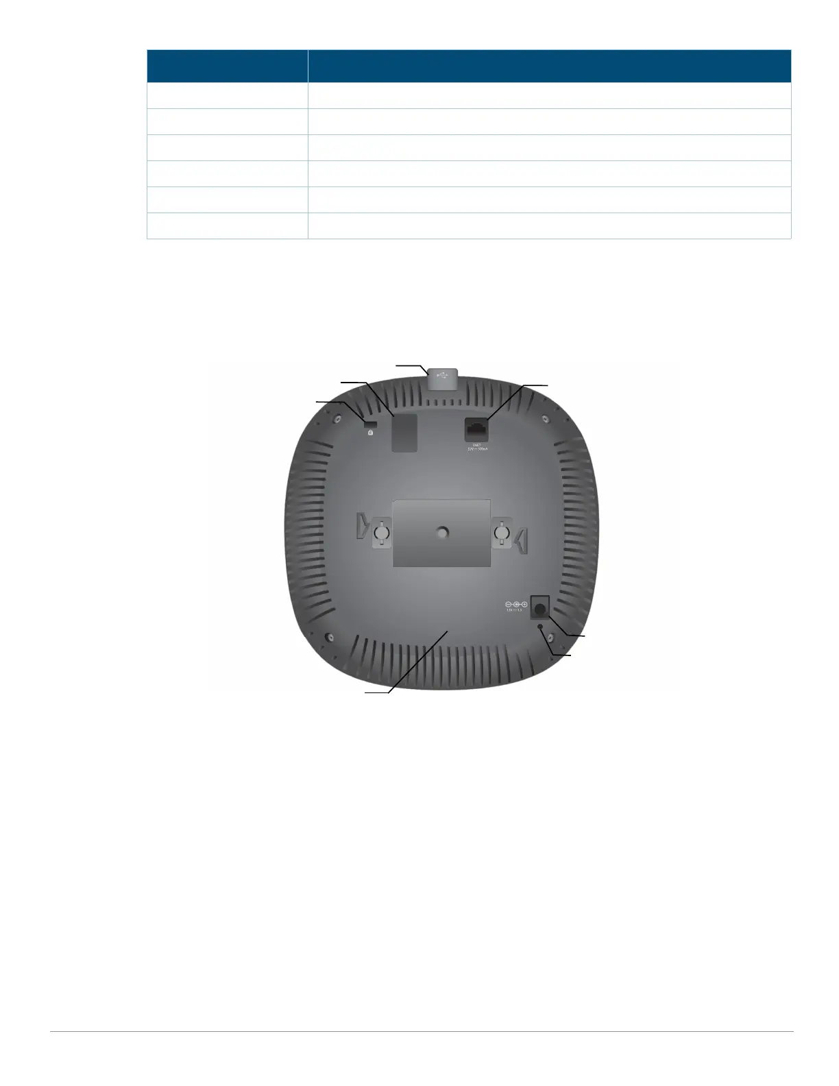
Figure 2 310 Series Access Point (rear view)
External Antenna Connectors
The AP-314 and IAP-314 access points are equipped with four external antenna connectors located
on the front corners of the access point (see Figure 3).
Green- solid Both radios enabled in access mode
Green- blinking One radio enabled in access mode; one radio disabled
Amber- solid Both radios enabled in monitor mode
Amber- blinking One radio enabled in monitor mode; one radio disabled
Green/Amber- alternating One radio in access mode; one radio in monitor mode
Red Both radios in error mode
Color/State Meaning
USB Port
Ethernet Port
Kensington
Console Port
Lock
DC Power
Socket
Reset Button
BLE Radio
A



 To Next Page