2 Aruba Instant On AP17 Access Points | Installation Guide
LED
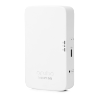
The AP17 access point is equipped with a LED that indicates the system status of the device. .
Reset Button
The reset button located on the bottom of the device can be used to reset the access point to factory default
settings or turn off/on the LED display.
There are two ways to reset the access point to factory default settings:
Reset the AP during normal operation
Press and hold down the reset button using a small, narrow object such as a paper clip for more than 10
seconds during normal operation.
Reset the AP while powering up
1. Press and hold down the reset button using a small, narrow object such as a paper clip while the access point
is not powered on.
2. Connect the power supply to the access point while the reset button is being held down.
3. Release the reset button on the access point after 15 seconds.
To turn off/on the LED display, press and release the reset button using a small, narrow object, such as a
paperclip for less than 10 seconds during normal operation of the access point.
Ethernet Ports
The AP17 access point is equipped with one 10/100/1000Base-T auto-sensing, MDI/MDX Ethernet port (E0) for
wired network connectivity. This port supports IEEE 802.3af Power over Ethernet (PoE), accepting 48Vdc
(nominal) as a standard defined Powered Device (PD) from a Power Sourcing Equipment (PSE) such as a PoE
midspan injector, or network infrastructure that supports PoE.
The port has an RJ-45 female connectors with the pin-out shown in Figure 2.
Figure 2 Gigabit Ethernet Port Pin-Out
Grounding Point
Always remember to protect the access point by installing grounding lines. The ground connection must be
complete before connecting power to the access point enclosure.
Table 1 AP17 Access Point LED Status
LED Color/State Meaning
System LED No Lights Device has no power
Blinking Green Device is starting
Alternating Green/Amber Device is ready for setup
Solid Green Device is ready
Solid Amber Device has detected a problem
Solid Red Device has an issue- immediate action required
1000Base-T Gigabit
Ethernet Port
RJ-45 Female
Pin-Out
Signal Name
1
2
3
4
5
6
7
8
BI_DC+
BI_DC-
BI_DD+
BI_DD-
BI_DA+
BI_DA-
BI_DB+
BI_DB-
Function
Bi-directional pair +C, POE Positive
Bi-directional pair -C, POE Positive
Bi-directional pair +D, POE Negative
Bi-directional pair -D, POE Negative
Bi-directional pair +A, POE Negative
Bi-directional pair -A, POE Negative
Bi-directional pair +B, POE Positive
Bi-directional pair -B, POE Positive