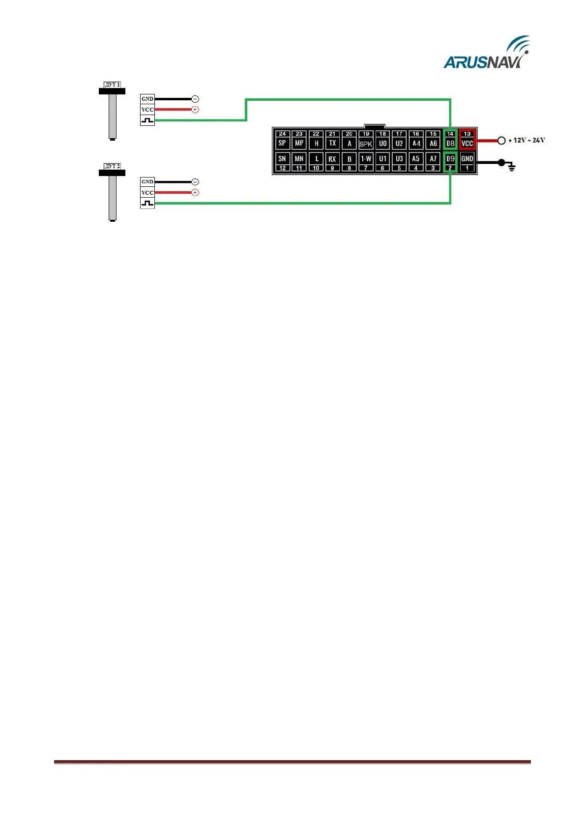
Fig. 5 – Frequency FLSs connection diagram
In the settings of the frequency FLS, specify the following parameters:
• Output signal type – frequency
• Frequency range: 30–4000 Hz
• Activate the pull-up resistor
When connecting frequency FLSs of other manufacturers, resistor pull-up may be required. The
nominal value of the resistor is selected based on the on-board voltage and output parameters of the
FLS.
‘Call button’ mode – input works as discrete. After activation of the input (including short-
term) will be made to dial the numbers listed in the device settings, in order of priority (from 1 to 5). In
the "phone numbers" web Configurator it is possible to adjust the sensitivity of the microphone and the
volume level of the speakers.
‘Control massa’ – mode is used on vehicles equipped with a ground switch. The input is shorted to
minus the power of the tracker. Used in conjunction with the "ignition"mode”. At the moment when the
ground is switched off, the "ignition" state is considered to not valid (parameter v_in=0).
‘Speed control output – mode is used on vehicles for control speed. If speed is more than entered in
field – output is go to active state. Output is deactivated after speed decrease less then entered level in field.