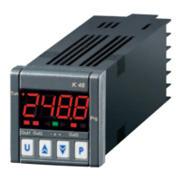
Do you have a question about the Ascon tecnologic K48 and is the answer not in the manual?
| Category | Controller |
|---|---|
| Output | Relay |
| Power supply | 12-24 Vac/Vdc |
| Display | Dual 4-digit display |
| Mounting | Panel |
| Dimensions | 48 x 48 mm |
| Operating Voltage | 12-24 Vac/Vdc |
Guidelines for correct instrument installation, considering accessibility and environmental factors.
Visual representation of electrical connections for inputs, outputs, and power supply.
Physical dimensions and cutout size required for panel mounting the controller.
Important precautions and rules for safe and accurate wiring of the instrument.
Configuration for thermocouple sensor input types, including cold junction compensation.
Configuration for infrared sensor input types, specifying impedance and compensation.
Configuration for RTD Pt100 sensor input, including line resistance compensation.
Configuration for thermistor sensor input, detailing input circuit and resistance.
Configuration for voltage and millivolt sensor inputs, specifying impedance and accuracy.
Configuration for 4-20mA input signals, supporting passive and active transmitters.
Configuration for digital logic inputs, outlining safety notes and dry contact operation.
Configuration details for the instrument's output channels, including relay and SSR options.
Configuration for Output 1, detailing relay and SSR specifications and logic levels.
Configuration for Output 2, detailing relay and SSR specifications and logic levels.
Configuration for Output 3, detailing relay and SSR specifications and logic levels.
Specifications and connection details for the instrument's power supply requirements.
Detailed technical specifications of the instrument, including physical, electrical, and environmental data.
Guide for selecting and ordering the correct instrument configuration based on options.
Overview of the instrument's setup process and parameter modification.
Explanation of password protection for parameter access levels and modification.
Describes instrument states and display behavior upon startup.
Step-by-step guide to access the instrument's configuration menu.
Procedure for safely exiting the configuration mode and returning to normal operation.
Details on using keyboard buttons for parameter value adjustment and navigation.
Steps to restore the instrument to its factory default settings.
General notes on parameter visibility and their relation to hardware configuration.
Parameters for configuring main and auxiliary sensor inputs.
Selection of the primary sensor input type (TC, RTD, mV, mA).
Setting the decimal point location for displayed measured values.
Defines the minimum displayed value for linear input scaling.
Defines the maximum displayed value for linear input scaling.
Setting the engineering units (°C or °F) for temperature measurements.
Applying a digital filter to smooth measured values for improved stability.
Defines instrument behavior for sensor over/under-range conditions.
Sets the output value to be applied during safety-related conditions.
Configures the operational function assigned to Digital Input 1.
Configures the operational function assigned to Digital Input 2.
Parameters for configuring and managing the instrument's output channels.
Configures the primary function of Output 1 (e.g., Heating, Cooling, Alarm).
Links specific alarm conditions to the activation of Output 1.
Defines the action mode (direct or reverse) for Output 1.
Configures the primary function of Output 2.
Links specific alarm conditions to the activation of Output 2.
Defines the action mode for Output 2.
Configures the primary function of Output 3.
Links specific alarm conditions to the activation of Output 3.
Defines the action mode for Output 3.
Configures the primary function of Output 4.
Links specific alarm conditions to the activation of Output 4.
Defines the action mode for Output 4.
Parameters for configuring and managing Alarm 1 functions and behavior.
Defines the type of Alarm 1 (e.g., high, low, band, sensor break).
Configures the behavior of Alarm 1 (e.g., latched, acknowledgeable).
Sets the lower threshold value for Alarm 1.
Sets the upper threshold value for Alarm 1.
Sets the general threshold value for Alarm 1.
Defines hysteresis for Alarm 1 to prevent rapid switching.
Sets a delay timer for Alarm 1 activation to avoid false triggers.
Enables Alarm 1 during specific instrument states like standby or out-of-range.
Parameters for configuring and managing Alarm 2 functions.
Defines the type of Alarm 2 (e.g., high, low, band).
Configures the behavior of Alarm 2.
Sets the lower threshold value for Alarm 2.
Sets the upper threshold value for Alarm 2.
Sets the general threshold value for Alarm 2.
Defines hysteresis for Alarm 2 to prevent rapid switching.
Sets a delay timer for Alarm 2 activation.
Enables Alarm 2 during specific instrument states.
Parameters for configuring and managing Alarm 3 functions.
Defines the type of Alarm 3.
Configures the behavior of Alarm 3.
Sets the lower threshold value for Alarm 3.
Sets the upper threshold value for Alarm 3.
Parameters for configuring and managing the Loop Break Alarm feature.
Explains the principle and operation of the Loop Break Alarm feature.
Sets the time parameter for the Loop Break Alarm.
Defines the delta measure for LBA during soft start.
Sets the delta measure for the LBA step.
Specifies conditions for enabling the LBA function.
Parameters for configuring the instrument's control algorithms.
Selects the primary control algorithm (e.g., PID, ON/OFF).
Options for selecting auto-tuning methods for PID control.
Initiates manual auto-tuning process for PID parameters.
Enables or disables the self-tuning adaptive algorithm for PID.
Sets hysteresis for ON/OFF control types to prevent rapid switching.
Sets a time delay for compressor protection to prevent short cycling.
Configures the proportional band (gain) for PID control.
Sets the integral time constant for PID control.
Sets the derivative time constant for PID control.
Manages fuzzy logic parameters for overshoot reduction.
Defines the actuator type (SSR, Relay, Slow) for the heating output.
Sets the minimum cycle time for the heating output actuator.
Defines the ratio of heating to cooling system efficiency.
Defines the actuator type (SSR, Relay, Slow) for the cooling output.
Sets the minimum cycle time for the cooling output actuator.
Sets a manual reset value to reduce undershoot during hot restarts.
Sets a delay before the instrument starts all functions after power-on.
Limits the maximum power output during the soft start phase.
Configures the duration of the soft start phase.
Sets a threshold value to automatically disable the soft start function.
Parameters for configuring and managing set point values and their behavior.
Specifies the total number of set points available for use.
Defines the minimum allowable value for any set point.
Defines the maximum allowable value for any set point.
Configuration for the primary set point value.
Configuration for the second set point value.
Configuration for the third set point value.
Configuration for the fourth set point value.
Selects which configured set point is currently active.
Defines how remote set points are received and processed.
Switches between local set point entry and remote set point control.
Sets the rate of temperature change for positive set point ramps.
Sets the rate of temperature change for negative set point ramps.
Parameters for configuring and managing the instrument's timer functions.
Configures the independent timer function and its operational modes.
Sets the time units (hours/minutes, minutes/seconds) for timer operations.
Sets the duration for the first timer interval.
Sets the duration for the second timer interval.
Monitors and controls the current status of the timer (Run, Hold, Reset).
Parameters for configuring and managing multi-step program execution.
Defines how programs initiate upon instrument power activation.
Sets engineering units for soak segments within program profiles.
Determines the instrument's action after a program finishes.
Configures how the instrument indicates the end of a program.
Defines the set point temperature for the first program soak segment.
Sets the rate of temperature change for the first program ramp segment.
Sets the duration for the first program soak segment.
Defines a temperature tolerance band for the first soak segment.
Configures event triggers for the first program group.
Defines the set point temperature for the second program soak segment.
Sets the rate of temperature change for the second program ramp segment.
Sets the duration for the second program soak segment.
Defines a temperature tolerance band for the second soak segment.
Configures event triggers for the second program group.
Defines the set point temperature for the third program soak segment.
Sets the rate of temperature change for the third program ramp segment.
Sets the duration for the third program soak segment.
Defines a temperature tolerance band for the third soak segment.
Configures event triggers for the third program group.
Defines the set point temperature for the fourth program soak segment.
Sets the rate of temperature change for the fourth program ramp segment.
Sets the duration for the fourth program soak segment.
Defines a temperature tolerance band for the fourth soak segment.
Configures event triggers for the fourth program segment.
Monitors and controls the current status of the program (Run, Hold, Reset).
Parameters related to the Human-Machine Interface and user access levels.
Sets a password for accessing limited operator functions.
Sets the password required for full configuration access.
Assigns specific functions to the 'U' button when the instrument is in runtime.
Configures the main display's content and behavior.
Enables or configures the bargraph display for showing process variable deviation.
Applies a filter specifically to the displayed value, not affecting control.
Determines the instrument's operating state and behavior upon power-up.
Controls which operative modes (Auto, Manual, Standby) are selectable.
Selects the current operative mode of the instrument.
Parameters for configuring serial communication settings.
Sets the unique address for the instrument on a serial communication bus.
Configures the serial communication speed (baud rate).
Defines data transmitted by a master unit in serial communication.
Parameters related to power consumption and energy measurement.
Selects the type of power or energy measurement (instantaneous, cumulative).
Sets the nominal voltage for accurate load power measurements.
Sets the nominal current for accurate load power measurements.
Sets a threshold for tracking instrument operating hours or days.
Parameters for calibrating the instrument's sensor inputs and outputs.
Calibrates the low end of the measurement range against a reference.
Adjusts the low offset value for improved measurement accuracy.
Calibrates the high end of the measurement range against a reference.
Adjusts the high offset value for improved measurement accuracy.
Process for defining custom user interfaces with different access levels.
Step-by-step guide to define parameter lists for limited and operator access.
Explains the different modes of operation available for the instrument.
Steps to access and modify parameters within the Operator level.
Steps to access parameters with limited access privileges.
Procedure to view limited access parameters without the ability to change them.
Details on operating the instrument in automatic control mode.
Describes keyboard functions available while operating in Auto mode.
Allows rapid modification of the active set point or current program segment set point.
Provides supplementary operational information and status indicators.
Explains the functionality and application examples of the programmer feature.
How to operate the instrument manually, controlling output power percentage.
How to operate the instrument as an indicator in standby mode.
Information on identifying and resolving instrument error conditions.
Explains indications for over-range and under-range measurement conditions.
Lists and describes potential instrument error codes and their meanings.
General information, safety precautions, and usage guidelines for the instrument.
Guidelines for correct and intended use of the instrument as per manual.
Information regarding product warranty coverage and the repair process.
Recommendations for routine instrument maintenance and cleaning procedures.
Details on optional accessories available for enhancing instrument functionality.



 Loading...