Ascon Tecnologic - K Series - ENGINEERING MANUAL - Vr. 9.0 PAG. 21
]Ser Group - Serial link parameters
[123] Add - Instrument address
Available: Always.
Range: oFF = Serial interface not used;
1... 254 Instrument address.
[124] bAud - Baud rate
Available: When [123] Add different from oFF.
Range: 1200 = 1200 baud;
2400 = 2400 baud;
9600 = 9600 baud;
19.2 = 19200 baud;
38.4 = 38400 baud.
[125] trSP - Selection of the value to be
retransmitted (Master)
Available: When [123] Add is different from oFF.
Range: nonE = Retransmission not used (the instrument is
a slave);
rSP = The instrument becomes a Master and
retransmits the operative set point;
PErc = The instrument becomes a Master and
retransmits the power output.
Note: For more details see [80] SP.rt (Remote set point type)
parameter.
]COn Group - Consumption parameters
[126] Co.tY - Measurement type
Available: Always.
Range: oFF = Not used;
1 = Instantaneous power (kW);
2 = Power consumption (kW/h);
3 = Energy used during program execution. This
measure starts from zero when the program is
launched and stops when the program ends.
A new program execution resets the value;
4 = Total worked days with threshold. Number of
hours that the instrument has been turned ON
divided by 24.
5 = Total worked hours with threshold. It is the
number of hours that the instrument has been
turned ON.
Note: Selections 3 and 4 use an internal counter for machine
service inspection intervals. The counter works every
time the instrument is turned ON. When the count
reaches the programmed threshold, the display shows
alternately the standard display and the message
r.iSP (requested Inspection). The count reset can be
done only by changing the threshold value.
[127] UoLt - Nominal Voltage of the load
Available: When [126] Co.tY = 1 or [126] Co.tY = 2 or
[126] Co.tY = 3.
Range: 1... 9999 (V).
[128] cur - Nominal current of the load
Available: When [126] Co.tY = 1 or [126] Co.tY = 2 or
[126] Co.tY = 3.
Range: 1... 999 (A).
[129] h.Job - Threshold of the working period
Available: When [126] Co.tY = 4 or [126] Co.tY = 5.
Range: oFF = Threshold not used;
1... 999 days;
1... 999 hours.
]CAL Group - User calibration group
This function allows to calibrate the complete measuring
chain and to compensate the errors due to:
– Sensor location;
– Sensor class (sensor errors);
– Instrument accuracy.
[130] AL.P - Adjust Low Point
Available: Always.
Range: From -1999 to (AH.P - 10) engineering units.
Note: The minimum differance between AL.P and AH.P is
10 engineering units.
[131] ALo - Adjust Low Offset
Available: Always.
Range: -300... 300 engineering units.
[132] AH.P - Adjust High Point
Available: Always.
Range: From (AL.P + 10) to 9999 engineering units.
Note: The minimum differance between AL.P and AH.P is
10 engineering units.
[133] AL.o - Adjust Low Offset
Available: Always.
Range: -300... 300 engineering units.
Example: Environmental chamber with an operative range
from 10 to + 100°C.
1. Insert in the chamber a reference sensor connected with
a reference instrument (usually a calibrator);
2. Start the control of the instrument and set a set point equal
to the minimum value of the operative range (e.g. 10°C).
When the temperature in the chamber is steady, take
note of the temperature measured by the reference
system (e.g. 9°C).
3. Set [130] AL.P = 10 (low working point) and
[131] ALo = -1 (the difference between the values readed
on the instrument and on the reference system).
Note that after this set, the instrument measured value is
equal to the measured value of the reference system.
4. Set a set point equal to the maximum value of the
operative range (e.g. 100°C). When the temperature
in the chamber is steady, take note of the temperature
measured by the reference system (e.g. 98°C).
5. Set [132] AH.P = 100 (high working point) and
[133] ALo = +2 (the difference between the values readed
on the instrument and on the reference system).
Note that after this set, the instrument measured value is
equal to the measured value of the reference system.
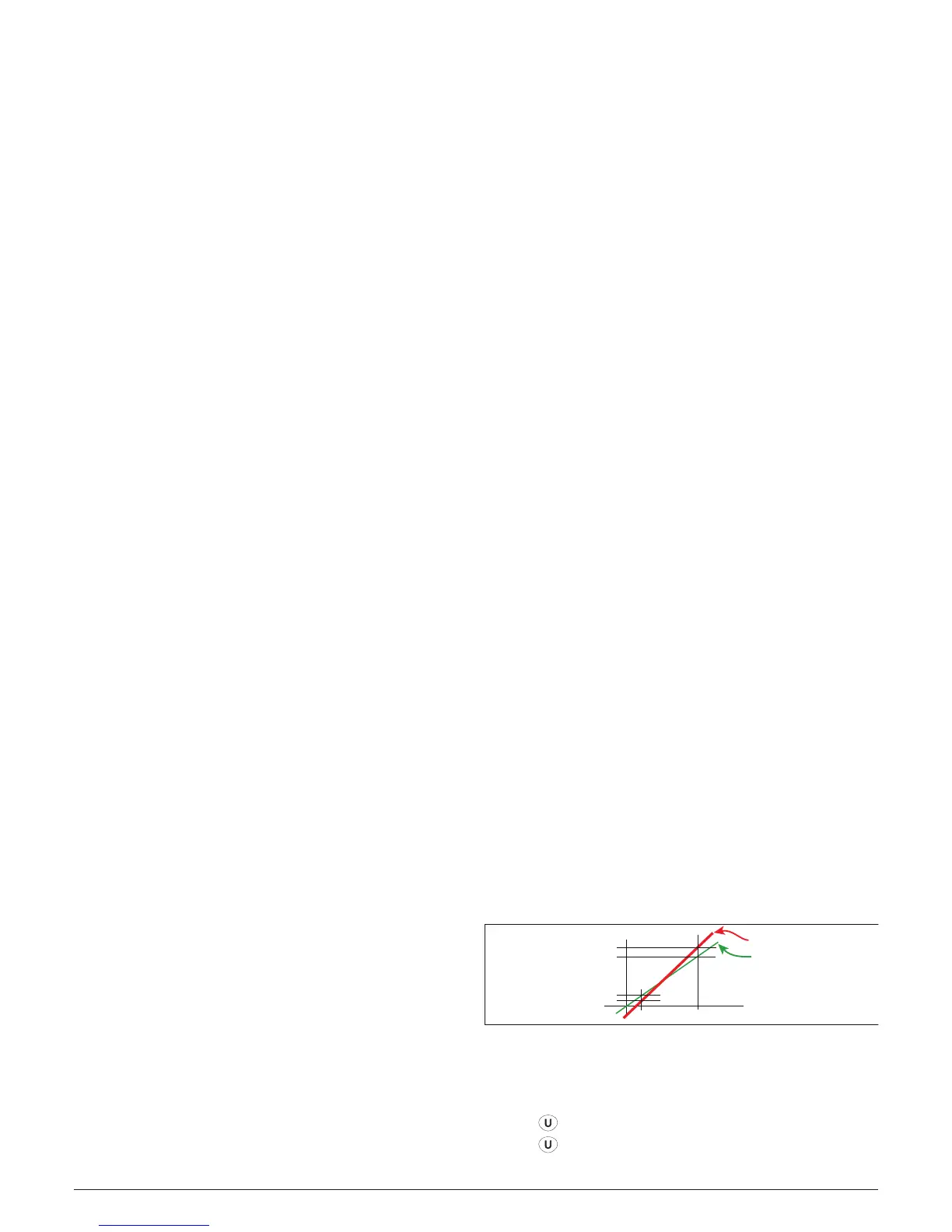
AH.P 100°C
AH.o = 2
AL.o = -1
AH.P 10°C
Real curve
Modified curve
The most important step of the configuration procedure is
completed.
In order to exit from configuration parameter procedure,
proceed as follows:
– Press
button;
– Press
button for more than 10 seconds;
– The instrument returns to the “Standard display”.