Ascon Tecnologic - K Series - ENGINEERING MANUAL -Vr. 9.0 PAG. 27
Appendix A
]
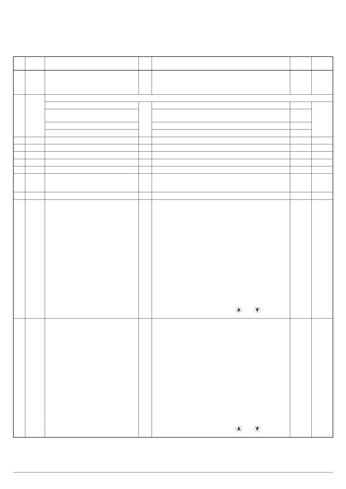
InP Group (Inputs Parameters)
no.
Para-
meter
Description Dec. Range Default
Vis.
Promo.
1 HcFG
Parameter available by serial link.
It shows the current hardware
0
TC/RTD
TC/PTC
Current
Voltage
Accor-
ding to
Hardw.
Not vis.
2 SEnS
Sensor selection (according to hardware)
TC, Pt100 input
0
J, crAL, S, r, t, ir.J, ir.cA, Pt1, 0.50 (mV), 0.60 (mV) 12.60 (mV)
J
A-4
TC, PTC, NTC input
J, crAL, S, r, t, Ir.J, Ir.cA, Ptc, ntc, 0.50 (mV), 0.60 (mV),
12.60 (mV)
Ptc
I input 0.20 (mA), 4.20 (mA) 4.20
V input 0.5(V), 1.5(V), 0.10(V), 2.10(V), 0.1 (V) 0.10
3 dP Decimal figures 0 0... 3 0 A-5
4 SSc Initial scale readout dP From -1999 to FSC (E.U.) -1999 A-6
5 FSc Final scale readout dP From SSc to 9999 (E.U.) 9999 A-7
6 unit Engineering unit 0 °c or °F 0 = °c A-8
7 FiL Digital filter on the measured value 1 From 0( oFF) to 20.0 (s) 1.0 C-0
8 inE
Selection of the Sensor Out of Range
type that will enable the safety output
value
0
or = Over-range
ur = Under-range
our = Over and Under
our C-0
9 oPE Safety output value 0 -100... 100 (%) 0 C-0
10 diF1 Digital input 1 function 0
oFF = No function
1 = Alarm Reset
2 = Alarm acknowledge (ACK)
3 = Hold of the measured value
4 = Stand by mode
5 = HEAt with SP1 and CooL with “SP2”
6 = Timer run/hold/reset [transition]
7 = Timer run [transition]
8 = Timer reset [transition]
9 = Timer run/hold [Status]
10 = Program run
11 = Program reset
12 = Program hold
13 = Program run/hold
14 = Program run/reset
15 = Instrument in Manual mode
16 = Sequential set point selection
17 = SP1/SP2 selection
18 = Set point Binary selection
19 = Digital inputs in parallel to
and keys
20 = Timer Run/Reset
nonE A-13
11 diF2 Digital input 2 function 0
oFF = No function
1 = Alarm Reset
2 = Alarm acknowledge (ACK)
3 = Hold of the measured value
4 = Stand by mode
5 = HEAt with SP1 and CooL with “SP2”
6 = Timer run/hold/reset [transition]
7 = Timer run [transition]
8 = Timer reset [transition]
9 = Timer run/hold [Status]
10 = Program run
11 = Program reset
12 = Program hold
13 = Program run/hold
14 = Program run/reset
15 = Instrument in Manual mode
16 = Sequential set point selection
17 = SP1 / SP2 selection
18 = Set point Binary selection
19 = Digital inputs in parallel to
and keys
20 = timer Run/Reset
nonE A-14