oFoF ÷ 999Access Password to
t.PP
73
00 ÷ 1Active mode:
0 = Normal
72
4oF / 1 / 2 / 3 / 5
/ 6
Set Visibility with fast
procedure by key P:
oF = None
1 = SP
2 = SPE
3 = SP e SPE
4 = Active SP
5 = SP and SPH
6 = SP, SPE and SPH
t.Ed
71
oFoF/ 0.01 ÷ 9.59
(min.sec ) ÷
30.0
(min.sec.x10)
Keyboard lock function
delay
70
oFoF / 1 / 2 / 3 / 4Function mode key
Down/Aux: see “t.UF”
69
oFoF / 1 / 2 / 3 / 4Function mode key U:
oF= No function
1= Auxiliary output
command
2= Norm. / Eco mode
Selection
3= Switch on/off
(Stand-by)
4= “Turbo” cycle
command
68
parameters relative to configuration of the keyboard
oFoF/ 0.01 ÷ 9.59
(min.sec ) ÷
99.5
(min.sec.x10)
Time relative to auxil-
iary output
67
oFoF / 1 / 2 / 3 / 4Function mode auxil-
iary output:
oF= No Function
1= control output “ot”
delayed
2= manual activation
by key or digital input.
3 = light with economy
mode (on in Normal
mode off in Eco mode)
4 = internal light (off
with door closed and
on with door opened)
o.Fo
66
oF = disable
1 = active alarms only
2 = key pressed only
3 = active alarms and
key pressed
PROBLEMS, MAINTENANCE AND GUARANTEE
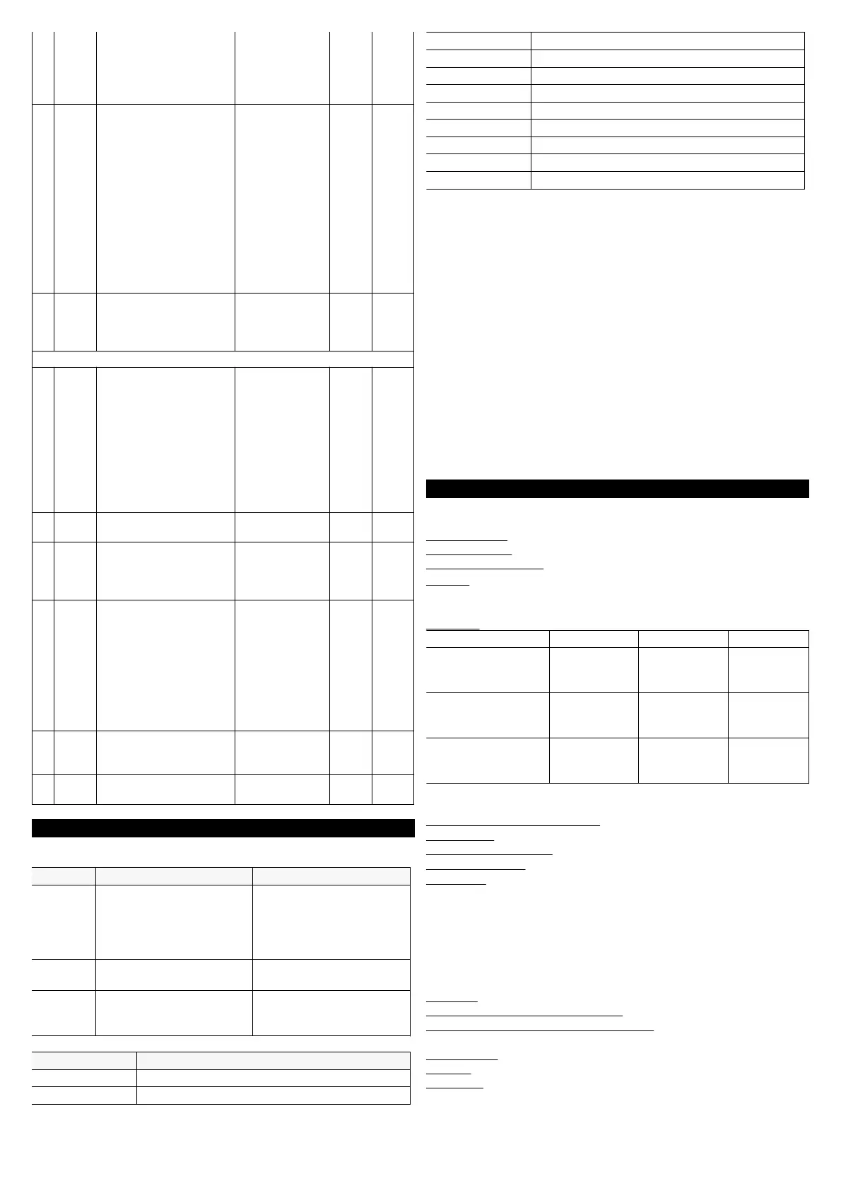
6.1 - SIGNALLING
Replace the instrument
or ship to factory for
Fatal memory error
Press key PInternal EEPROM
EPr
Check the correct
connection of the probe
with the instrument and
check the probe works
The probe may be
interrupted (E) or in
short circuit (-E), or may
measure a value outside
E2 -E2
E3 -E3
Action ReasonError
Other Signalling:
Keyboard lock
Delay at power-on in progress
ReasonMessage
“turbo” mode active
Eco mode active
Eco
Post-defrosting in progress with “d.dL”=Lb
PdF
Defrosting in progress with “d.dL”=Lb
Door opened
Digital input alarm in progress
noF
Digital input alarm in progress
AL
Minimum temperature alarm in progress
Maximum temperature alarm in progress
6.2 - CLEANING
We recommend cleaning of the instrument only with a slightly wet
cloth using water and not abrasive cleaners or solvents.
6.3 - GUARANTEE AND REPAIRS
The instrument is under warranty against manufacturing flaws or
faulty material, that are found within 12 months from delivery date.
The guarantee is limited to repairs or to the replacement of the
instrument.
The eventual opening of the housing, the violation of the instrument
or the improper use and installation of the product will bring about
the immediate withdrawal of the warranty’s effects.
In the event of a faulty instrument, either within the period of
warranty, or further to its expiry, please contact our sales
department to obtain authorisation for sending the instrument to
our company.
The faulty product must be shipped to ASCON TECNOLOGIC with
a detailed description of the faults found, without any fees or
charge for ASCON TECNOLOGIC, except in the event of
alternative agreements.
7.1 - ELECTRICAL DATA
Power supply: 115 VAC, 230 VAC, 12...24 VAC/VDC +/- 10%
Frequency AC: 50/60 Hz
Power consumption: 3,5 VA approx.
Input/s: 3 inputs for temperature probes: PTC (KTY 81-121, 990 Ω
@ 25 °C) or NTC (103AT-2, 10KΩ @ 25 °C); 1 digital input for free
voltage contacts (alternative to Pr3 input)
Output/s: up to 3 relay outputs
2 A
Gen.Use
2 (1) A5 (1) AOut3 - SPST-NO -
5A - 1/10HP
10 A Res.8 (4) A8 (3) AOut2 - SPDT - 8A
- 1/2HP 250V,
14 A Res.,
96 LRA,
16 FLA
14 (14) A30 (15) AOut1 - SPST-NO -
30A - 2HP 250V,
1HP 125 VAC
UL 60730EN 60730EN 61810
16 A Max. for common (pin. 1), 12 A Max. for extractable terminal
block model
Electrical life for relay outputs: 100000 op. (EN60730)
Action type: type 1.B (EN 60730-1)
Overvoltage category: II
Protection class : Class II
Insulation: Reinforced insulation between the low voltage part
(supply C or D type and relay output) and front panel; Reinforced
insulation between the low voltage section (supply C or D type and
relay output) and the extra low voltage section (inputs); Reinforced
between supply G and relay output; No insulation between supply
G type and inputs.
7.2 - MECHANICAL DATA
Housing: Self-extinguishing plastic, UL 94 V0
Heat and fire resistance category : D
Ball Pressure Test secondo EN60730: acessible parts 75 °C;
support live parts 125 °C
Dimensions:
78 x 35 mm, depth 64 mm
Weight: 190 g approx.
Mounting: Incorporated Flush in panel (thickness max. 12 mm) in
71 x 29 mm hole
ASCON TECNOLOGIC - Y33 - OPERATING INSTRUCTIONS - Vr. 01 - 04/16 - ISTR-MY33-ENG01 - PAG. 13