Ascon Tecnologic - Y39 Line - Operating Instructions - Pag. 10
When the EP evaporator probe is used, the fans are con-
ditioned by parameters F.tn, F.tF and F.FE as well as are
conditioned by the temperature control.
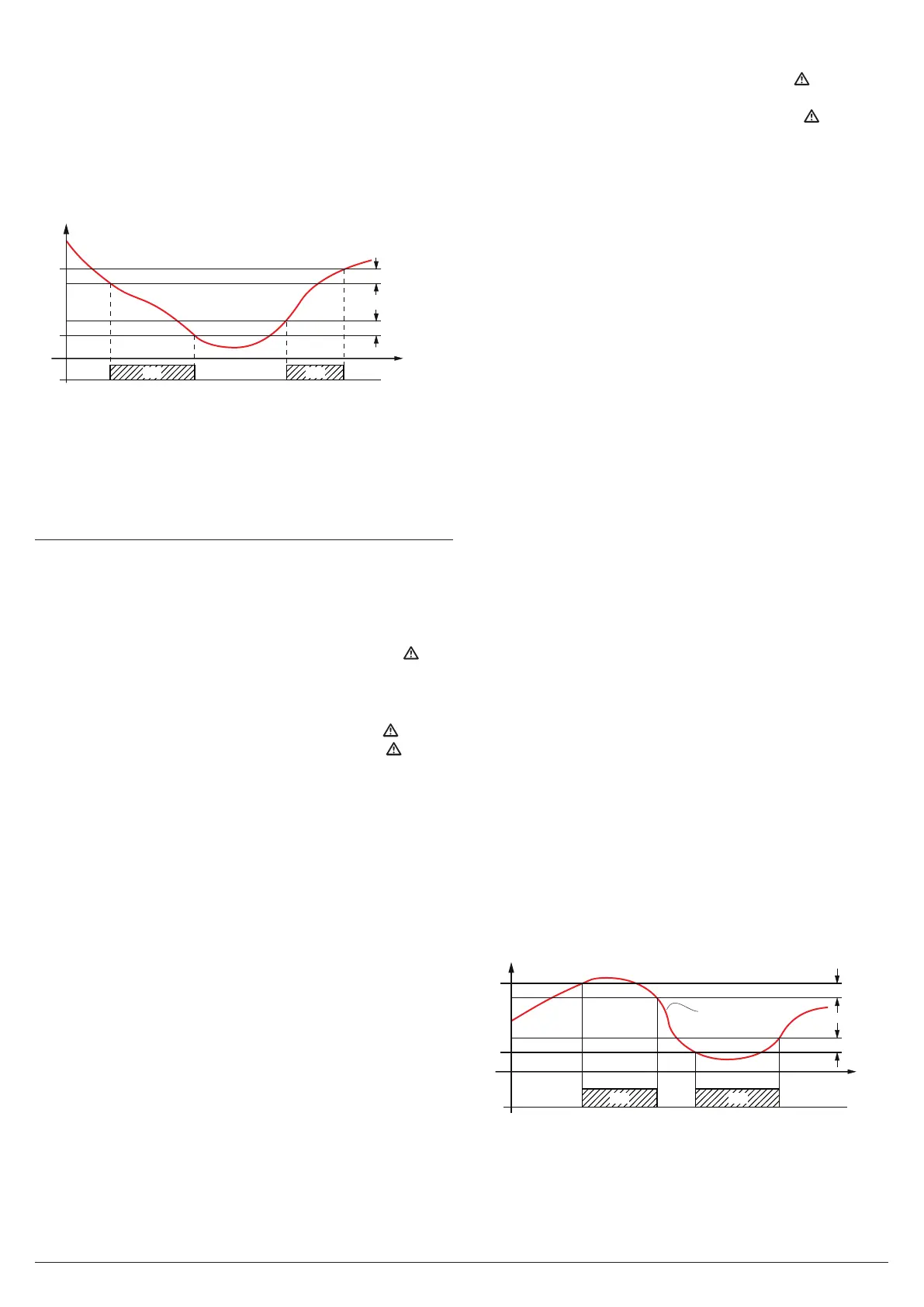
It is possible to disable the fans when the temperature meas-
ured by the evaporator probe is higher than the one set with
parameter F.FL (temperature too hot) or is lower than the one
set at parameter F.LF (temperature too cold).
Associated with these parameters there is also their differen-
tial that can be set with parameter F.dF.
Fn
F.LF
Ep
F.FL
F.dF
F.dF
time
offoff offON ON
Remember that the fans functioning can be conditioned by
the Door open function operated by the digital input.
Note: It is necessary to pay attention to the correct use of
this fans temperature control functions because in the
typical application of refrigeration the evaporator fans
stop, also stops the thermal exchange.
5.10 Alarm Functions
The alarm conditions of the instrument are:
– Probe errors: E1, -E1, E2, -E2, E3, -E3;
– Temperature alarms: Hi and Lo;
– External alarm: AL;
– Open door alarm: oP.
The instrument alarm functions act on the alarm LED
, on
internal buzzer (if present and programmed by parameter
o.bu) and on the desired output, if configured with param-
eters
o.o1, o.o2 or o.o3
according to the parameters set.
All alarm conditions are pointed out lighting up the
LED,
while the silenced or stored alarms are shown with
LED
flashing.
The buzzer (if o.bu = 1 or 3) is activated in alarm condition
and can be manually disabled pressing any instrument key
(alarm silencing).
The possible selections of output parameters for the alarm
signalling function are:
At
The output must be activated in alarm condition and can
be manually deactivated by pressing any key of the instru-
ment (typical application for an acoustic signal)
;
AL The output must be activated in alarm condition but
cannot be manually disabled; the alarm status ends
when the alarm condition ceases (typical application for
a light signal);
An
The output must be activated in alarm condition and must
remain active when the alarm has ceased. The disabling
action (recognition of a stored alarm) can only be carried
out manually by pressing any key when the alarm status
has ended (typical application for light signal);
-t Function similar to At but with inverse logic function
(output active in normal conditions, disabled in alarm).
-L
Function similar to AL but with inverse logic function
(output active in normal conditions, disabled in alarm).
-n
Function is similar to An but with inverse logic function
(output active in normal conditions, disabled in alarm).
The instrument is equipped with the “alarm memory” function
which can be activated via the A.tA parameter. A.tA values are:
oF The instrument disables the alarm signal (
)
when the
alarm status ends;
on The instrument maintains the alarm signal (
)
when
the alarm status ends.
To cancel the alarm memory signal, press any key.
It must be remembered that if an output function is desired
with an alarm memory (
o.o1, o.o2, o.o3
= An or = -An) it is
necessary to set the parameter A.tA = ON.
5.10.1 Temperature Alarms
The temperature alarms work according to the programmed
probe measurement, the type of alarm set at parameter A.Ay,
the alarm thresholds at parameters A.HA (maximum alarm)
and A.LA (minimum alarm) and the relative differential A.Ad.
Through parameter A.Ay it is possible to set if alarm thresh-
olds A.HA/A.LA are to be considered as Absolute or Relative to
the Set Point , if the reference temperature must be related to
Pr1 or Au probe and if the message Hi (maximum alarm)/Lo
(minimum alarm) is to be displayed at alarm intervention.
The possible selections of the parameter A.Ay are:
1 Pr1 Absolute Alarms with Hi/Lo label;
2 Pr1 Relative Alarms with Hi/Lo label;
3 Au probe Absolute Alarms Hi/Lo label;
4 Au probe Relative Alarm Hi/Lo label;
5 Pr1 Absolute Alarms with no label;
6 Pr1 Relative Alarms with no label;
7 Au probe Absolute Alarms with no label;
8 Au probe Relative Alarms with no label.
Using some parameters it is also possible to delay the ena-
bling and the intervention of these alarms.
These parameters are:
A.PA
Temperature alarm intervention delay at instrument
power ON when the instrument is in alarm status at
power ON. If the instrument is not in alarm status at
power ON, A.PA is not considered.
A.dA
Temperature alarm exclusion time at the end of de-
frost cycle (and, if programmed, after the draining) or
after a continuous cycle.
A.At
Temperature alarms delay activation time. Tempera-
ture alarms are enabled at the end of the exclusion
times and are activated after the A.At time when the
temperature measured by the probe exceeds or goes
below the respective maximum and minimum alarm
thresholds. The alarm thresholds are those set at
parameters A.HA and A.LA when the alarms are set as
absolute (A.Ay = 1, 3, 5, 7);
AL
A.LA
A.HA
A.Ad
A.Ad
time
offoff off
ON ON
Hi Lo
PR1 (or AU)
or assume the values [SP + A.HA] and [SP + A.LA] if the
alarms are relative (A.Ay = 2, 4, 6, 8).