Ascon Tecnologic - Y39 Line - Operating Instructions - Pag. 7
disabled. In this mode, the Aux output can be turned
OFF automatically after a certain time that can be set ON
the parameter o.tu. With o.tu = oF the output is activated
and deactivated only manually, using a key
,
, or via
the digital input. Differently, the output, once activated, is
turned OFF automatically after the otu time. This mode
of operation can be used as a control of the shop window
lighting, anti-fogging resistors or other utilities.
3. Light output managed by Active Set Point (“eco” function).
This output will be ON in “Normal” mode (Set Point SP
active) and OFF in economy (eco) mode operation (Set
Point SP2 active).
4. Internal Light output managed by digital input. The output
will be ON when door is opened (i.Fi= 5, 6).
The internal buzzer (when present) can be configured by
parameter o.bu to carry out the following functions:
oF
Buzzer always disabled;
1 The Buzzer sounds when an alarm is active;
2 The Buzzer sounds when a key pressed (no alarm);
3 The Buzzer sounds when a key pressed and when an
alarm is active.
5.5 Active Set Point Selection
The instrument allows up to 2 different Set Points to be pre-set
(SP and SP2) and then choose which one is to be made Active.
This function can be used if it is necessary to switch be-
tween two different temperatures (e.g. day and night or posi-
tive and negative etc). The Active Set Point can be selected:
– Using the parameter S.SA;
– Using the key
/
(parameter t.UF = 3;
– Using the key
/Aux
(parameter t.Fb = 3);
– Using the Digital Input (parameter i.Fi = 8 or 11).
The selection of the Active Set point can be combined also
with the Switch OFF Auxiliary output function if used as light
(o.Fo = 3) and to change between Heating/Cooling action via
the digital input (i.Fi = 11).
SP and SP2 can be set to a value between the values pro-
grammed with parameters S.LS and S.HS.
Note: In the examples that follow, the Set point is generally
indicated as SP, but the instrument will work accord-
ing to the Set point selected as active.
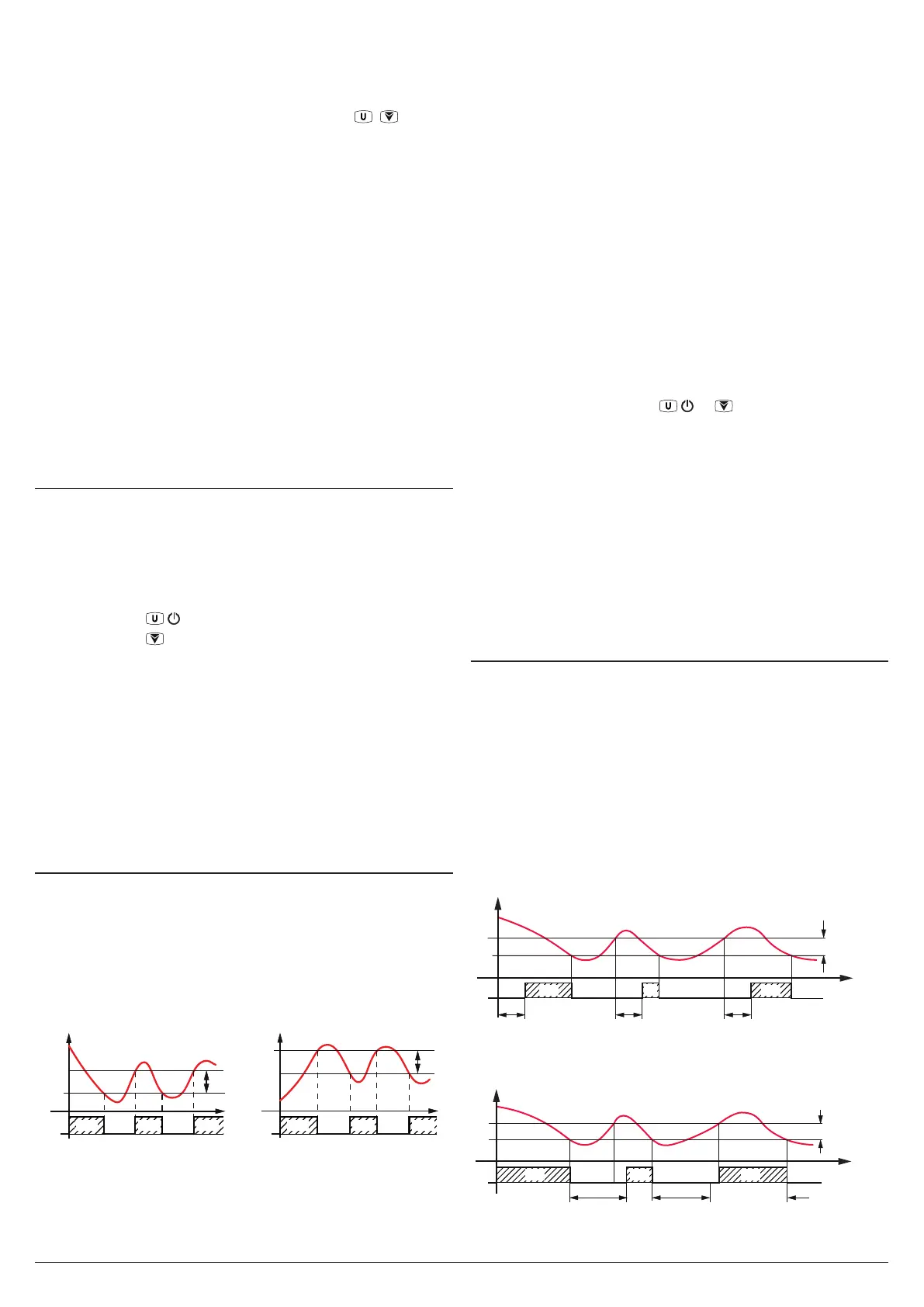
5.6 Temperature Control
The instrument control is ON/OFF and acts ON the output
configured as ot depending on the measure of probe Pr1,
the active Set Point (SP or SP2), the differential (hysteresis)
r.d and the action r.HC.
Depending ON the function mode programmed with param-
eter r.HC the differential is automatically considered by the
controller with positive values for Cooling actions (r.HC = C)
or with negative values for Heating actions (r.HC = H).
r.HC
OUT
ot
SP
Temp.
r.d
time
r.HC
offoff
SP
r.d
ON ON ON
OUT
ot
offoff
ON ON ON
time
Pr1
Temp.
Pr1
In the event of probe error, it is possible to set the instrument
so that the output continues working in cycles according to
the times programmed with parameters r.t1 (activation time)
and r.t2 (deactivation time).
If a probe error occurs, the instrument activates the output
for the r.t1 time, then deactivates it for the r.t2 time and so
on whilst the error remains.
Programming r.t1 = oF the output, in probe error condition,
remains switched OFF.
Programming instead r.t1 to any value and r.t2 = oF the
output, in probe error condition, remains switched ON.
The instrument has a continuous cycle function through
which is possible to mantain active the ot control output for
the time set at parameter r.tC, regardless the temperature
controller command.
The function can be used, for example, when a rapid tem-
perature drop of the product is required after the refrigerator
has been loaded.
It should be noted that during the continuous cycle defrosts
are inhibited and the temperature alarms are disabled
throughout the whole cycle and also subsequently for the
time set at parameter A.dA.
The start of a continuous cycle can only take place through a
manual command using the / or /Aux keys (t.UF or t.Fb
= 2) or via the digital input (i.Fi = 3) if properly programmed.
The continuous cycle in progress is indicated on the display
with the indication CC and can be stopped by further action
(as for activation) on the button or on the digital input.
The continuous cycle function cannot be activated during
defrosts and with r.tC = oF.
Remember that the temperature control function can be
conditioned by the “Compressor Protection and output delay
at power-on”, “Defrost”, “Door open” and “External alarm with
outputs disable” functions.
5.7 Compressor Protection Function and
Delay at Power-ON
The “Compressor Protection” function aims to avoid close
compressor start ups controlled by the instrument in Cooling
applications.
This function provides 3 time controls. These control func-
tions manage the switching ON of the output configured as
ot associated with the temperature control request.
The protection consists of preventing the output being
enabled (switched ON) during the times set with parameters
P.P1, P.P2 and P.P3 and therefore that any activation occurs
only after all the times have elapsed.
First control (parameter P.P1) foresees a delay to the ot out-
put activation (switching ON delay).
SP
Pr1
of
ffoff
P.P1
off
ON ONON
Temp.
time
P.P1 P.P1
r.d
Out
ot
Second control (parameter P.P2) inhibits the activation of ot
output by a time delay (P.P2) that starts when the output is
turned OFF (delay after switching-OFF).
SP
Out
ot
of
ffoff
ON ON
time
P.P2 P.P2
r.d
P.P2
ON
Pr1
Temp.