Ascon Tecnologic - Y39 Line - Operating Instructions - Pag. 5
4.3 Electrical Connections
Carry out the electrical wiring by connecting only one wire to
each terminal, according to the following diagram, checking
that the power supply is the same as that indicated ON the
instrument and that the load current absorption is no higher
than the maximum electricity current permitted.
As the instrument is built-in equipment with permanent con-
nection inside housing, it is not equipped with either switches
or internal devices to protect against overload of current: the
installation will include an overload protection and a two-
phase circuit-breaker, placed as near as possible to the in-
strument, and located in a position that can easily be reached
by the user and marked as instrument disconnecting
device which interrupts the power supply to the equipment.
It is also recommended that the supply of all the electrical
circuits connected to the instrument must be properly pro-
tected, using devices (ex. fuses) proportionate to the circulat-
ing currents.
It is strongly recommended that cables with proper insula-
tion, according to the working voltages and temperatures are
to be used.
Furthermore, the probe input cable must be kept separate
from line voltage wiring.
When a probe shielded cable is used, the protection shield
should be connected to ground at only one side.
Whether the instrument is a 12/24 V version (Power supply
code F/G) it is recommended to use an external TCTR trans-
former, or with equivalent features (class II insulation) and to
use only one transformer for each instrument because there
is no insulation between supply and input.
m
We recommend that a check should be made that the
parameters are those desired and that the application
functions correctly before connecting the outputs
to the actuators so as to avoid malfunctioning that
may cause irregularities in the plant that could cause
damage to people, things or animals.
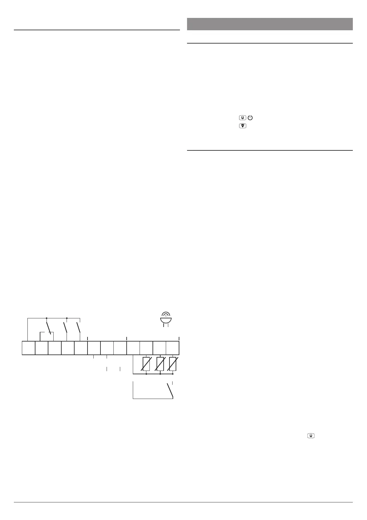
4.3.1 Electrical Wiring Diagram
1
2
3
4
5
6
7
8
9
10
11
12
Internal
Buzzer
Pr1 Pr3Pr2
Digital
Input
12... 24 VAC/VDC
100... 240 VAC
Power supply Inputs
NONONCNOC
Out2 Out1 Out3
Out1: 16A-AC1 (6A-AC3)/250V)
Out2: 8A-AC1 (3A-AC3)/250V)
Out3: 5A-AC1 (2A-AC3)/250V)
16A max. for relays common terminal (C)
(12A max. for those with removable terminal block).
5 FUNCTIONS
5.1 ON/STAND-BY Function
Once powered the instrument can assume 2 different conditions:
ON: The controller uses the control functions.
STAND-BY: The controller uses no control function and the
display is turned OFF except for the Stand-by LED.
The transition between Standby and ON status is equivalent
to power ON the instrument providing the electrical power.
In case of power failure, the system always sets itself in the
condition it was in before the black-out.
The ON/Stand-by function can be selected:
– Pressing the key
/
for at least 1 s if t.UF = 4;
– Pressing the key
/Aux
for at least 1 s if t.Fb = 4;
– Using the Digital Input if parameter i.Fi = 10.
5.2 Measure and Display configuration
Through parameter i.SE it is possible to select the type of
probes that that is to be used. The probe type can be:
thermistors PTC KTY81-121 (Pt) or NTC 103AT-2 (nt).
With parameter i.uP it is possible to select the tempera-
ture engineering unit and the desired measure resolution
(C0 = °C/1°; C1=°C/0.1°; F0 = °F/1°; F1 = °F/0.1°).
The instrument allows the measure calibration, which can be
used to re-calibrate the instrument according to application
needs, through the parameters i.C1 (for input Pr1), i.C2 (for
input Pr2) and i.C3 (for input Pr3).
The function carried out by Pr2 and Pr3 probes is defined by
parameters i.P2 and i.P3. These parameters can be config-
ured for the following functions:
EP
Evaporator probe: used to managing the defrost and
the evaporator fans (see relative functions);
Au Auxiliary probe;
dG Digital input (see Digital input functions);
If probe Pr2 and/or Pr3 is/are not used, set the relative pa-
rameters i.P2 and/or i.P3 = oF.
It is not possible to program the two parameters for the same
function, if so, priority goes to i.P2.
Using i.Ftparameter can be set a software filter for measur-
ing the input values in order to decrease the sensibility to
rapid temperature changes (increasing the sampling time).
Through the idS parameter is possible to set the variable
normally displayed:
P1
Probe Pr1 measurement;
P2 Probe Pr2 measurement;
P3 Probe Pr3 measurement;
SP Active set point value;
oF Numerical display switched OFF.
When one of the measures is displayed (i.dS = P1/P2/P3)
the i.CU parameter allows to set an offset that is to be ap-
plied only to the displayed variable (all controls will always
made according to the correct temperature value, changed
only by the calibration parameters i.C1, i.C2, i.C3).
The normally displayed value is established by parameter
i.dS, but, repeatedly pressing and releasing
key
,
it is
possible to display all the variables and also the Pr1 high
and low peak measurement values. The display alternately
shows the code that identifies the variable and its value.
The variables that can be displayed are:
Pr1
Pr1 probe temperature;
Pr2 Pr2 probe temperature (on/oF if set as Digital input);
Pr3 Pr3 probe temperature (on/oF if set as Digital input);