Ascon Tecnologic - Z31A - Operating Instructions - Pag. 6
5.5 Alarm Functions
The alarm conditions of the instrument are:
– Probe errors: E1, -E1;
– Temperature alarms: Hi and Lo.
The instrument alarm functions act on the alarm LED ( ), on
internal buzzer (if present and programmed by parameter o.bu).
All alarm conditions are pointed out lighting up the
LED,
while the silenced or stored alarm is shown with the LED
flashing.
o.bu parameter configures the internal buzzer as follws:
oF Internal buzzer disabled;
1. The buzzer sounds when an alarm is active;
2. The buzzer sounds when a key pressed (no alarm);
3. The buzzer sounds when a key pressed and when an
alarm is active.
The buzzer (if o.bu = 1 or 3) is activated in alarm condition
and can be manually disabled pressing any instrument key
(alarm silencing).
5.5.1 Temperature Alarm
The temperature alarm works according to the programmed
probe measurement, the type of alarm set at parameter A.Ay,
the alarm thresholds at parameters A.HA (maximum alarm)
and A.LA (minimum alarm) and the relative differential A.Ad.
Through parameter A.Ay it is possible to set if alarm thresholds
A.HA/A.LA are to be considered as Absolute or Relative to the
Set Point. The possible selections of the parameter A.Ay are:
1. Absolute Alarm;
2. Relative Alarm.
Using the parameters that follow it is also possible to delay
the enabling and the intervention of the alarm.
A.PA
Temperature alarm intervention delay at instrument
power ON when the instrument is in alarm status at
power ON. If the instrument is not in alarm status at
power ON, A.PA is not considered.
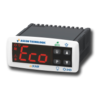
A.At
Temperature alarm delay activation time. Temperature
alarm is enabled at the end of the exclusion time and
is activated after the A.At time when the temperature
measured by the probe exceeds or goes below the re-
spective maximum and minimum alarm thresholds. The
alarm thresholds are those set at parameters A.HA and
A.LA when the alarms are set as absolute (A.Ay = 1);
AL
A.Ad
A.Ad
time
offoff off
ON ON
Hi Lo
Pr1
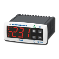
or assume the values [SP + A.HA] and [SP + A.LA] if the
alarms are relative (A.Ay = 2).
AL
SP
Pr1
A.Ad
A.Ad
time
offoff off
ON ON
Hi Lo
The maximum and minimum temperature alarms can be
disabled setting A.HA and A.LA = oF.
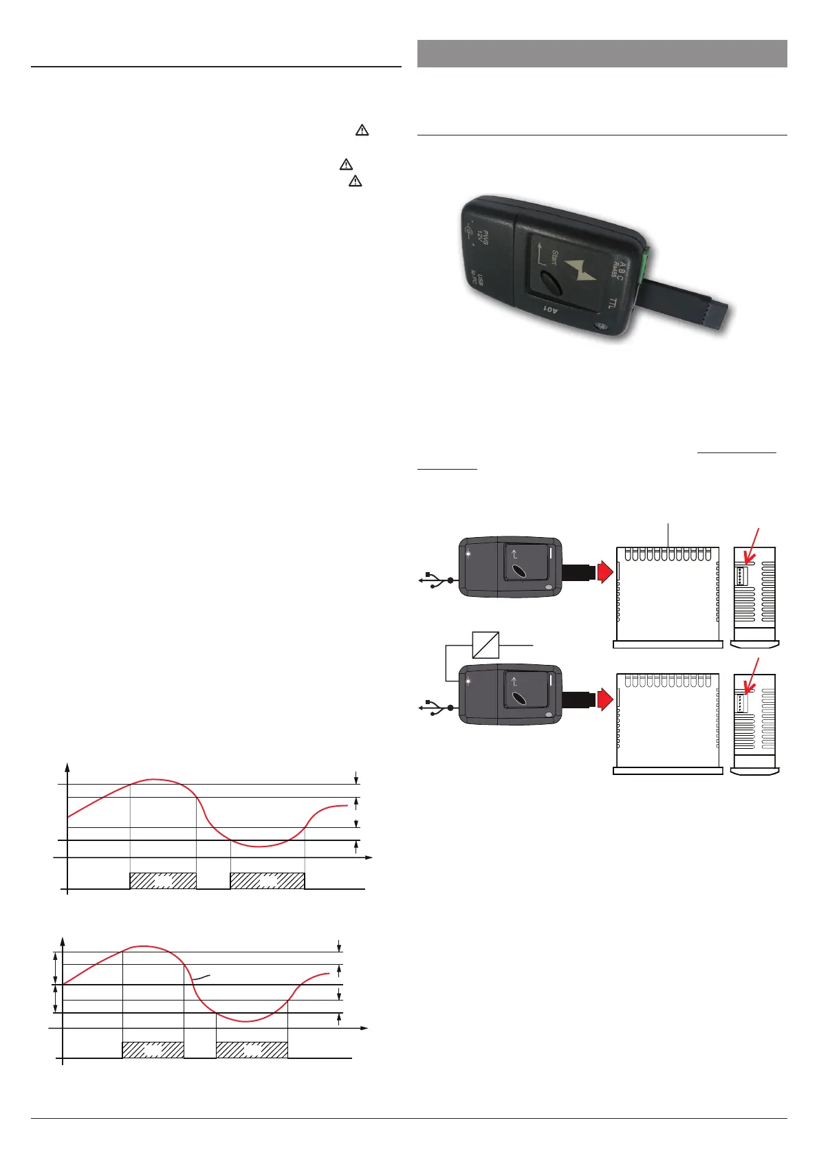
6 ACCESSORIES
The instrument is equipped with a connector that allows the
connection to some accessories.
6.1 Parameters Configuration by A01
The instrument is equipped with a 5 poles connector that
allows the transfer from and toward the instrument of the
functioning parameters through the device A01.
This device it is mainly usable for serial programming those
instruments that need the same parameters configuration or
to keep a copy of the parameters setting of an instrument and
allow its fast duplication.
The same device allows to connect a PC via USB with which,
through the appropriate configuration software “AT Universal-
Conf tools”, the operating parameters can be configured.
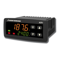
To use the A01 device it is necessary that the device or instru-
ment are being correctly supplied.
AC supply
Supply adapter
12 VDC
supply
Enter
PWS
12 V
A B C
TTL
+-
USB
to PC
B
Enter
PWS
12 V
A B C
TTL
+-
USB
to PC
B
For additional info, please look at the A01 instruction manual.