Ascon Tecnologic - Z31A - Operating Instructions - Pag. 5
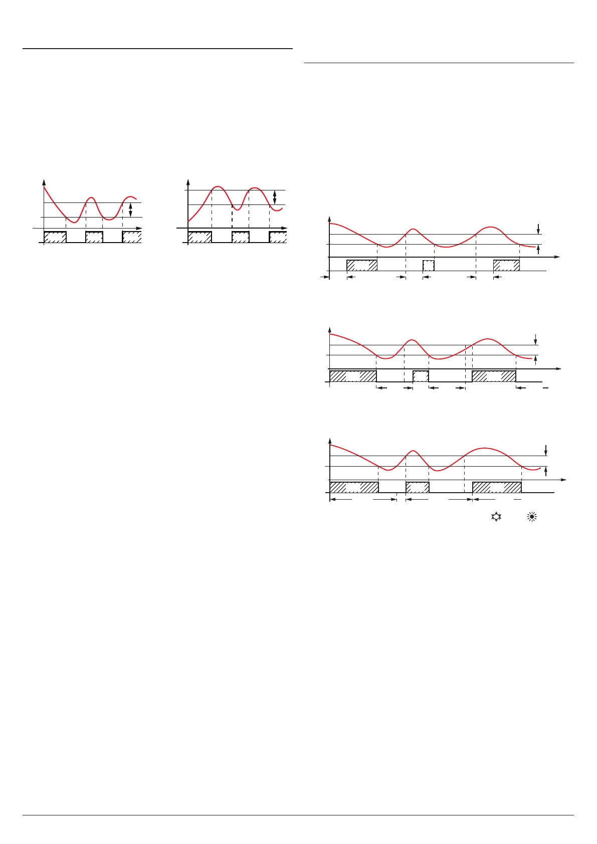
5.3 Temperature Control
The instrument control is ON/OFF and acts on the output
depending on the probe measurement, the active Set Point
(SP), the intervention differential (r.d)(hysteresis) and the
r.HC action type selected. Depending ON the function mode
programmed with parameter r.HC the differential is auto-
matically considered by the controller with positive values
for Cooling actions (r.HC = C) or with negative values for
Heating actions (r.HC = H). Through the r.HC parameter the
following action types can be selected:
Cooling (r.HC = C) Heating (r.HC = H)
r.HC
SP
Temp.
r.d
time
r.HC
offoff
SP
r.d
ON ON ON
OUT
offoff
ON ON ON
Pr1
Temp.
Pr1
In the event of a probe error, it is possible to set the instru-
ment so that the output continues working in cycles ac-
cording to the times programmed at the parameters r.t1
(activation time) and r.t2 (deactivation time). When a probe
error occurs the instrument activates the output for r.t1 time,
then deactivates it for r.t2 time and so on whilst the error
remains. Programming r.t1 = oF the output, in probe error
condition, remains switched OFF. Programming instead
r.t1 to any value and r.t2 = oF the output in probe error
condition remains switched ON.
Remember that the temperature control function can be
conditioned by the Compressor Protection and output delay
at power-ON functions.
5.4 Compressor Protection Function and
Delay at Power-ON
The “Compressor Protection” function aims to avoid those
close compressor start ups requested by the instrument in
Cooling applications or, in any case, it can be used to add a
time control on the output intended for commanding the ac-
tuator. The “Compressor Protection” function provides 3 time
controls that manage the switching ON of the output.
The protection consists of preventing the output being
enabled (switched ON) during the protection times set with
parameters P.P1, P.P2 and P.P3 and therefore that any activa-
tion occurs only after all the times have elapsed.
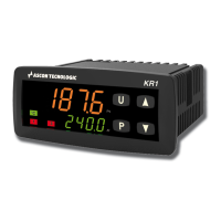
First control (P.P1) foresees an output activation delay
(switching ON delay).
SP
time
offoff off off
ON
ON
r.d
P.P1
P.P1
ON
Pr1
P.P1 P.P1
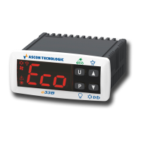
Second control delays the activation of the output by a time
(P.P2) that starts when the output is turned OFF (delay after
switching-OFF).
offoff off
ON
SP
time
r.d
P.P2
ON ON
Pr1
P.P2 P.P2 P.P2
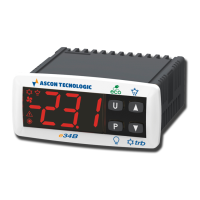
Third control delays the activation of the output by a time
(P.P3) that starts when the output was turned ON last time
(delay between switching-ONs).
offoffoff
ON
SP
time
r.d
P.P3
P.P3 P.P3
P.P3
ON ON
Pr1
During output inhibition the OUT LED (Cool /Heat ) blinks.
It is also possible to prevent the output activation after the in-
strument is turned ON for the time set at parameter P.od.
During power ON delay phase, the display shows the label
od alternated with the normal visualization.
All these functions are disabled if the relative parameters are
set to OFF (oF).