Ascon Tecnologic - Z31A - Operating Instructions - Pag. 4
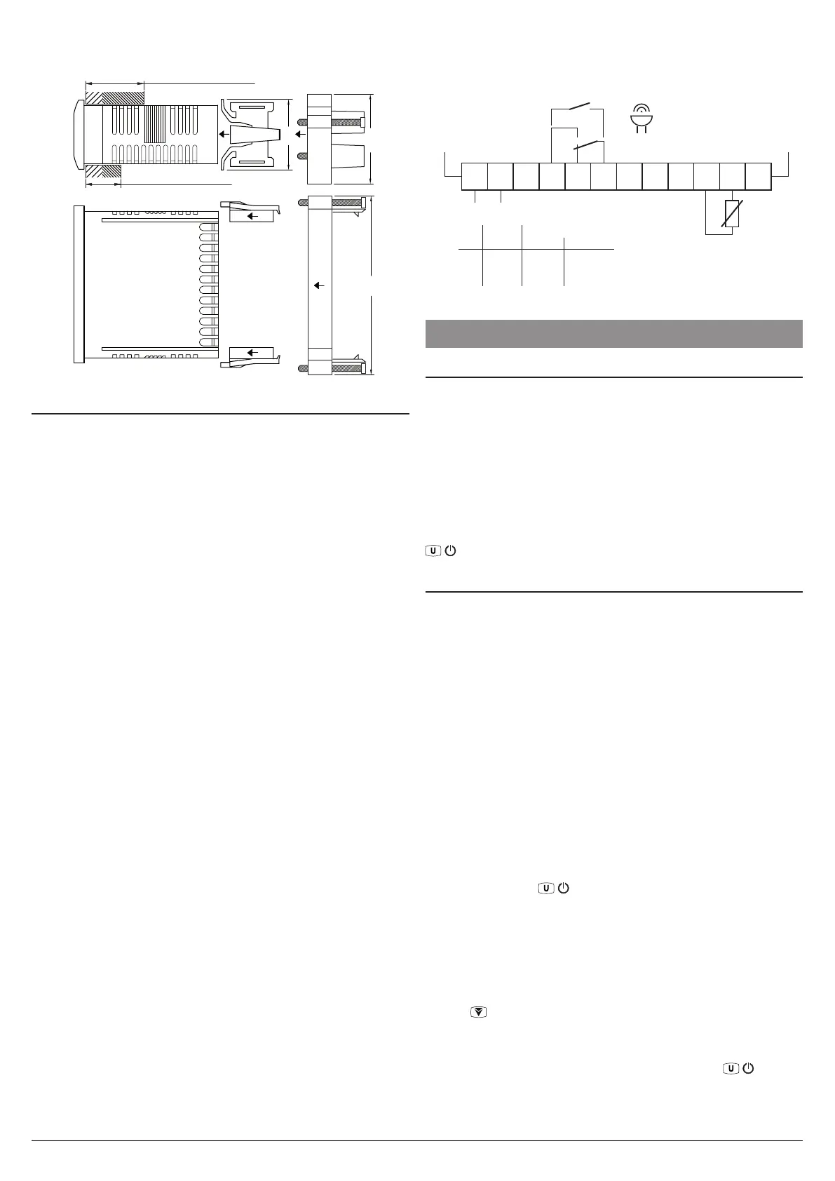
4.2.3 Brackets
Type 2: gasket max. 12 mm
Type 1: gasket 29 mm max.
34
43
Type 2
Type 1
“Butterfly” type
brackets
Screw type
bracket
86
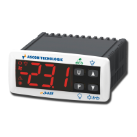
4.3 Electrical Connections
Carry out the electrical wiring by connecting only one wire to
each terminal, according to the following diagram, checking
that the power supply is the same as that indicated on the
instrument and that the load current absorption is no higher
than the maximum electricity current permitted.
As the instrument is built-in equipment with permanent con-
nection inside housing, it is not equipped with either switches
or internal devices to protect against overload of current: the
installation will include an overload protection and a two-
phase circuit-breaker, placed as near as possible to the in-
strument, and located in a position that can easily be reached
by the user and marked as instrument disconnecting device
which interrupts the power supply to the equipment.
Further recommendations:
– The supply of all the electrical circuits connected to the
instrument must be properly protected using devices (ex.
fuses) proportionate to the circulating currents;
– Use cables with proper insulation, according to the working
voltages and temperatures;
– Make sure that the input sensor cables are kept separate
from line voltage wiring in order to avoid induction of elec-
tromagnetic disturbances;
– If some cables are shielded, the protection shield must be
connected to ground at only one side;
– For those instruments with 12 or 24 V power supply (codes
f or g) it is necessary to use an external TCTR trans-
former, or equivalent (Class II insulation), and to use only
one transformer for each instrument because there is no
insulation between supply and input.
m
Before connecting the outputs we recommend to check
t
hat the parameters are those desired and the application
operates correctly the actuators so as to avoid malfunc-
tioning which may cause irregularities in the plant and
could cause damage to people, animals or things.
4.3.1 Electrical Wiring Diagram
Internal
Buzzer
Probe
1
2
3
4
5
6
7
8
9
10
11
12
Power supply
Input
NC C
SPDT
C
NO
NO
SPST-NO
10A Res.
Out1 16 (9)A 10 (4)A 30 LRA
5 FLA
(common: 12A max. for those with removable terminal blocks)
61810
EN
60730
EN UL
Z31A
16A-AC1 (6A-AC3)/250 VAC;
1HP 250VAC, 1/2HP 125VAC
Output
5 FUNCTIONS
5.1 ON/STAND-BY Function
Once powered the instrument can assume 2 different conditions:
ON: The controller uses the control functions.
STAND-BY: The controller uses no control function and the
display is turned OFF except for the Stand-by LED.
The transition between Standby and ON status is equivalent
to power ON the instrument providing the electrical power.
In case of power failure, the system always sets itself in the
condition it was in before the black-out.
The ON/Stand-by function can be selected: pressing the key
/
for at least 1 s if t.UF = 4;
5.2 Measuring Inputs and Display
With i.SE parameter is possible to select the type of probe
connected to the instrument:
Pt Thermistors PTC KTY81-121;
nt NTC 103AT-2.
Using i.uP parameter is possible to select the temperature
unit of measurement and the desired resolution (C0 = °C/1°,
C1 = °C/0.1°, F0 = °F/1°, F1 = °F/0.1°).
The instrument allows to re-calibrate the measurements to
adapt the instrument according to the application needs,
through parameter i.C1.
Using i.Ft parameter can be set a software filter for the
measuring the input values in order to decrease the sensibil-
ity to rapid temperature changes (increasing the time).
The instrument normally displays the temperature measured
by the probe but it is possible to visualise the highest and
lowest Pr1 peak measurement values in rotation by pressing
and releasing key
/
. The display shows the code that
identifies the variable alternated to its value:
Lt and the lowest Pr1 peak temperature;
Ht and the highest Pr1 peak temperature.
Pr1 and the temperature read by the probe;
When the instrument is switched OFF, the peak values are
reset, however, it is possible to reset these values also by us-
ing the key hold pressed for 3 s during peak visualization.
The display shows “---” and the peak memory will be reset.
The instrument automatically exits the variables display mode af-
ter about 15 seconds from the last pressure on the / button.