Ascon Tecnologic - Z31A - Operating Instructions - Pag. 3
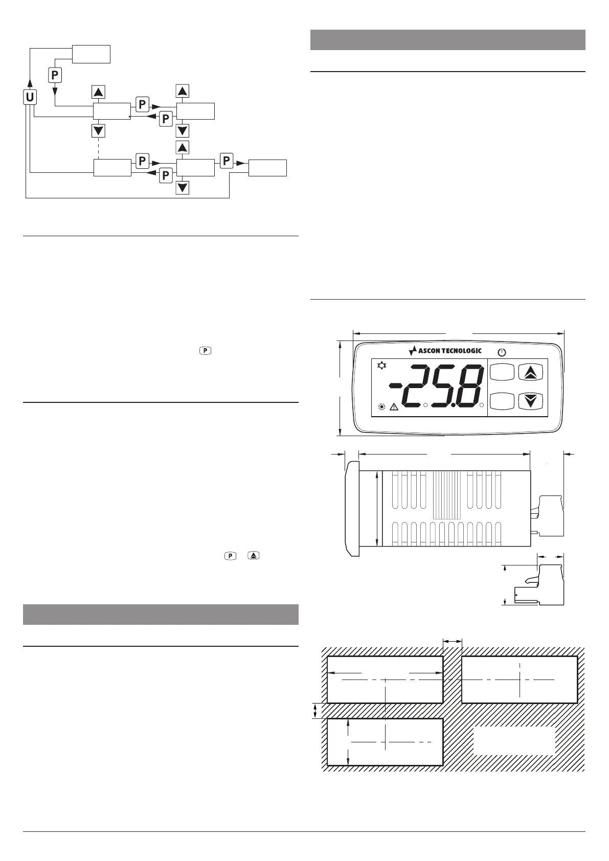
Previous
Param.
Not protected
parameters
Set parameter
Next
Param.
Increase
value
Decrease
value
A.HA.
35.0
s.ls.
-25.5
0.
Password
request
Parameter
(Program mode)
Correct
password
inserted
2 s
5 s
Increase
value
Decrease
value
r.p.
Insert password
2.5 Reset Parameters to Default Value
The instrument allows the reset of the parameters to those
values programmed in factory as default.
To restore the default parameters value, set the value -48 at
r.p password request.
Therefore, to make the reset to the default parameters, en-
able the Password using the t.PP parameter so that the r.p
setting is requested, at this point insert -48 instead of the
programmed access password.
Once confirmed the password with the
key, the display
shows “---” for 2 s after which the instrument resets all the
parameters to the factory default setting.
2.6 Keyboard Lock Function
On the instrument it is possible to completely lock the key-
board. This function is useful when the controller is installed
in an accessible area and changes must be avoided.
To activate the keyboard lock it is enough program the pa-
rameter t.Lo to a value different than oF.
The t.Lo value is the keys inactivity time after which the in-
strument automatically locks the keyboard.
Therefore, press-
ing no buttons for the time set at t.Lo, the normal functions of
the keys are automatically disabled.
When the keyboard is locked, if any of the key is pressed,
the display shows Ln to indicate that the lock is active.
To unlock the keyboard it is enough to press
+ keys at
the same time and keep them pressed for 5 s, after which
the label LF appears on the display and all the key functions
will be available again.
3 USAGE WARNINGS
3.1 Admitted Usage
m
The instrument has been projected and manufactured
as a measuring and control device to be used accord-
ing to EN60730-1 at altitudes operation below 2000 m.
The use of the instrument for applications not expressly
permitted by the above mentioned rule must adopt all the
necessary protective measures.
The instrument MUST NOT BE USED in dangerous (flamma-
ble or explosive) environments without adequate protections.
m
The installer must ensure that EMC rules are respected,
also after instrument installation, if necessary using
proper filters.
4 INSTALLATION WARNINGS
4.1 Mechanical Mounting
The instrument, in case 78 x 35 mm, is designed for flush-
in panel mounting. Make a hole 71 x 29 mm and insert the
instrument, fixing it with the provided special brackets.
In order to obtain the declared front protection degree, use
the screw type bracket (optional).
– Avoid installing the instrument in places where high humidity
can generate condensation or where dirt could lead to the
introduction of conductive substances into the instrument.
– Ensure the adequate ventilation to the instrument and
avoid the installation within boxes where are placed de-
vices which may overheat or have, as a consequence, the
instrument functioning at temperature higher than allowed
and declared.
– Connect the instrument as far as possible from source of
electromagnetic disturbances so as motors, power relays,
relays, electrovalves, etc..
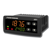
4.2 Dimensions [mm]
4.2.1 Mechanical Dimensions
P
U
Z31SA
35
28
14.5
8
4.2.2 Panel Cut-Out
29
+0.6
71
+0.6
mm
RECOMMENDED
PANEL CUTOUT