23
4 - Operation
4.3.1 PARAMETERS
The controller parameters have been organised in group, according to their functionality area.
1st stored
Setpoint
2nd stored
Setpoint
Values of the two Setpoints, that are
activated by mean of digital inputs,
communication parameters, and key-
board. The Setpoint active is indicat-
ed by the â or ä green led.
Setpoint
low limit
Setpoint
high limit
High and low limit of the Setpoint SP.
The minimum span (sp1-sp2) must
be greater than 100 digit.
Setpoint
ramp up
Setpoint
ramp down
This parameter specifies the maxi-
mum rate of change of the Setpoint.
Its units are: digit/s, digit/min and
digit/hour.
When the parameter is Off , this
function is disabled and the new
Setpoint value is reached immediately
after being entered (through the key-
board, the digital inputs and the ser-
ial communication). Otherwise, the
#s.l. d
#s.l. u
#s.p. H
#s.p. l
#s.p. 2
#s.p. 1
value entered is reached according
to the configured rate of change.
Remote
Setpoint Ratio
This parameter defines the maximum
span of the Remote Setpoint.
Remote
Setpoint Bias
It defines the low range of the Remote
Setpoint, in engineering units.
#bias.
#rtio
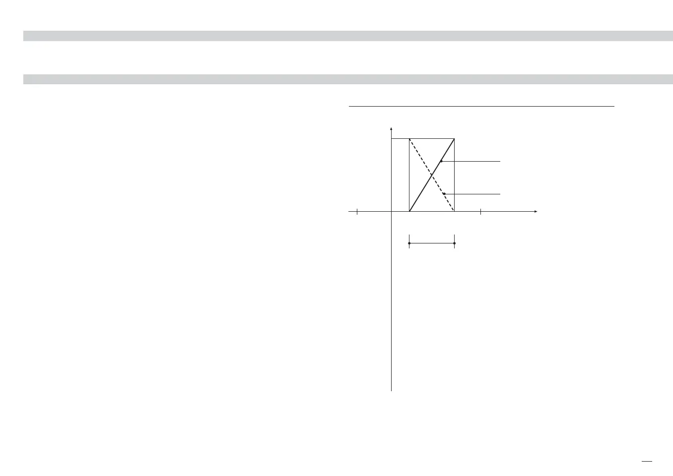
SETPOINT MENU
Remote Setpoint Bias and Ratio
bias = 20
ratio = 0.1
ratio = –0.1
Remote
signal
Range
600
100
20
0
Remote
Setpoint span
10V
bias = 100
a b
a´ b´
-200
°C
HR
a (b
´ ) b (a´ )
LR
PV = Process variable
LR = PV low limit
HR = PV high limit
SR = Remote Setpoint
a (a´) = SR starting point
b (b´) = SR ending point
M5 UK•ed4 10-12-2004 16:20 Pagina 23

 Loading...

