30 31
English
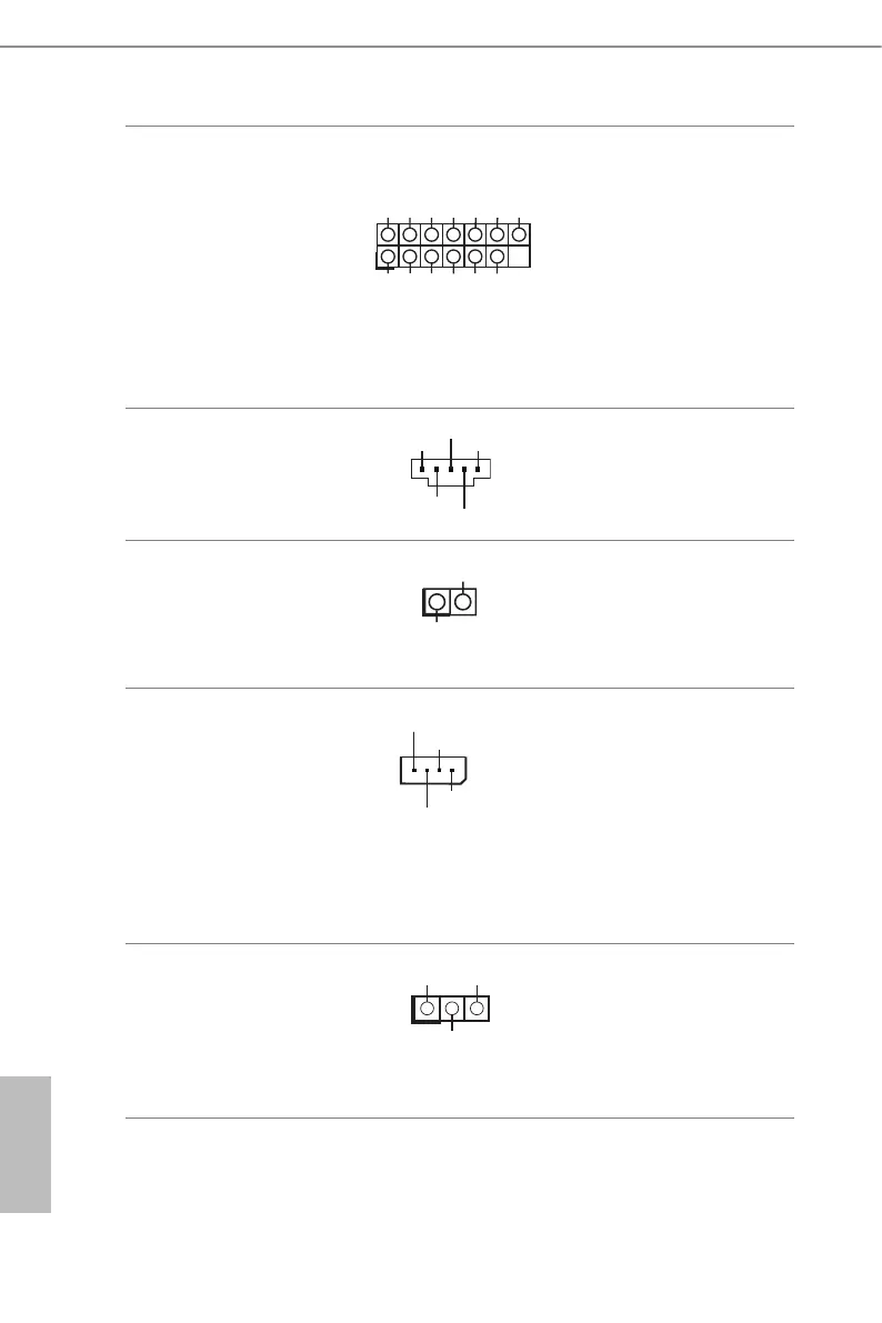
TPM Header
(13-pin TPM1)
(see p.7, No. 30)
+3V
+3V
GND
LAD3
LFRAME
GND33M
RST
LAD0
LAD2
GND
+3V
LAD1
1
is connector supports
Trusted Platform Module
(TPM) system, which can
securely store keys, digital
certicates, passwords, and
data. A TPM system also helps
enhance network security,
protects digital identities, and
ensures platform integrity.
PSU SMBus
(PSU_ SMB1)
(see p.7, No. 6)
+3V
1
GND
SMBCLK
SMBDATA
PSU SMBus monitors the
status of the power supply, fan
and system temperature.
Non Maskable Interrupt
Button Header
(NMI_ BTN1)
(see p.7, No. 36)
1
CONTROL
GND
Please connect a NMI device
to this header.
Intelligent Platform
Management Bus Header
(4-pin IPMB1)
(see p.7, No. 33)
IPMB_SCL
GND
No connect
This 4-pin connector is used
to provide a cabled base-board
or front panel connection for
value added features and 3rd-
party add-in cards, such as
Emergency Management cards,
that provide management
features using the IPMB.
ermal Sensor Header
(3-pin TR1)
(see p.7, No. 32)
1
TR1 TR1
GND
Please connect the thermal
sensor cable to either pin 1-2
or pin 2-3 and the other end to
the device which you wish to
monitor its temperature.
 Loading...