EPC602D8A / EPC602D8A-V+
29
English
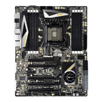
CPU Fan Connector
(4-pin CPU_FAN1)
(see p.7, No. 10)
GN D
+ 12V
CPU_FAN_SPEED
FAN_SPEED_CONTROL
1
2
3
4
is motherboard provides
a 4-Pin CPU fan (Quiet Fan)
connector. If you plan to
connect a 3-Pin CPU fan,
please connect it to Pin 1-3.
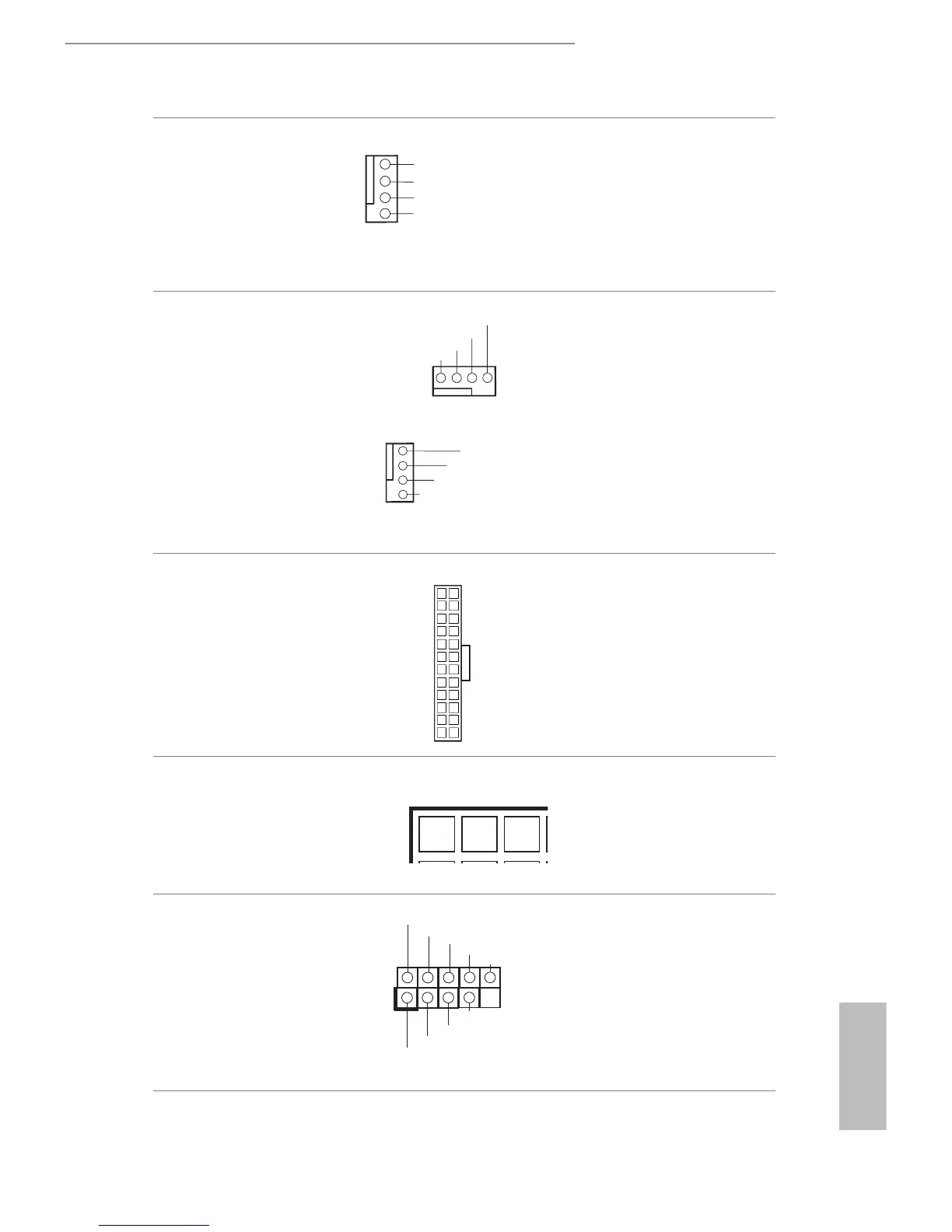
Front and Rear Fan
Connectors
(4-pin FRONT_FAN1)
(4-pin FRONT_FAN2)
(4-pin FRONT_FAN3)
(see p.7, No. 7, 12, 21)
(4-pin R EAR _FAN1)
(see p.7, No. 1)
Please connect fan cables to the
fan connectors and match the
black wire to the ground pin.
All fans support Fan Control.
ATX Power Connector
(24-pin ATXPWR1)
(see p.7, No. 8)
is motherboard provides a
24-pin ATX power connector.
To use a 20-pin ATX power
supply, please plug it along Pin
1 and Pin 13.
ATX 12V Power
Connector
(8-pin ATX12V1)
(see p.7, No. 6)
GND
RXTPBM_0
RXTPAP_0
GND
RXTPBP_0
+12V
+12V
GND
Besides one default IEEE
1394 port on the I/O panel,
there is one IEEE 1394 header
(1394_2) on this motherboard.
is IEEE 1394 header can
support one IEEE 1394 port.
12
1
24
13