ASSA ABLOY motor locks installation guide
7
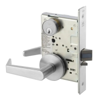
1 Connect the lock case to the I/O Box.
2 Set the function DIP switches on the lock case to the
desired settings.
3 Connect power to the I/O Box; the LED will flash
green/red to show that the power is on.
4 Set DIP switch 1 to ON. Set the configuration DIP
switch 2 for the desired operation.
5 When the red LED glows steadily the Hi-O bus is
secure and encrypted.
Setting up lock case and I/O Box
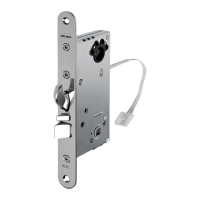
1 Connect the lock case and DAC.
2 Make sure the termination jumper in DAC is in the
ON position.
3 In most cases the Door monitor input should be
fitted with a jumper and the Button input should be
open. (For more information, see the setting-up
table.)
4 Set all DIP switches to the OFF position for most
applications. (For more information, see the
setting-up table.)
5 Turn on the power. (Blue DWG LED starts flashing.
Wait until blue DWG LED flashes rapidly, which can
take up to 3 minutes. Do NOT turn off the power
during setting up.)
6 Setting up is complete when the yellow PWR LED
lights up and the blue LED flashes rapidly. (If the blue
LED flashes rapidly and the yellow PWR LED does not
light up then setting up has failed.)
7 Turn off the power.
8 Set DIP switch 8 to ON for standalone mode.
Also see page 12 for different operating modes.
9 Turn the power back on and check operation.
Setting up lock case and DAC564/DAC530
 Loading...