34 Issue 2008-11-13 1004935-US-1.0
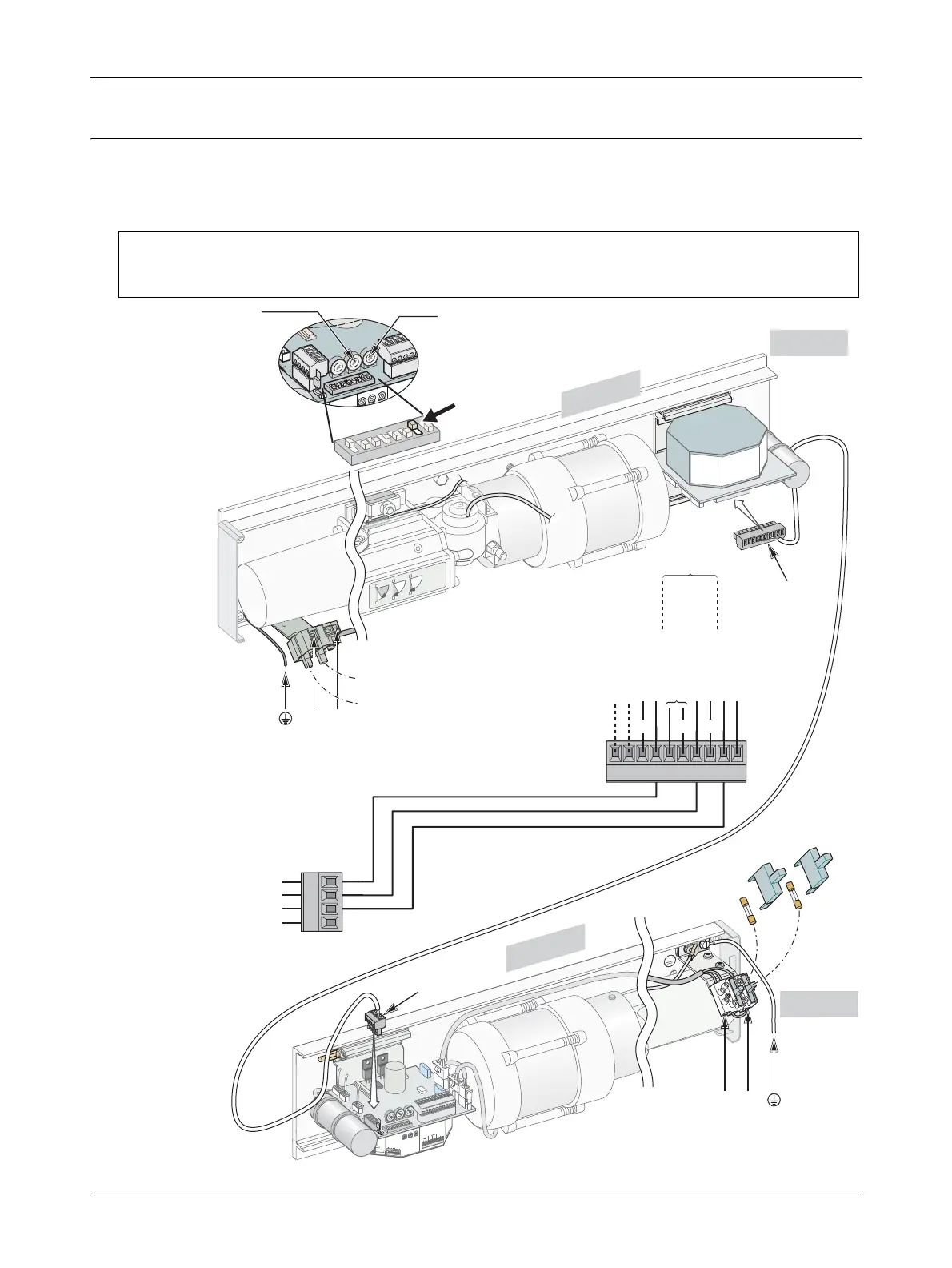
11.3 Connection of Control Units CSDB/CSDB – double doors
For double door operators both operators have to be connected to the mains. A three-
pole cable (not enclosed) has to be connected between TB1 on the CSDB (master)
and TB2 on the CSDB (slave).
HSO
HSO
LSO
LSCLK
HSC
HSC
LSC
701448
LK
1
TB2
TB2
5
6
7
8
9
1
0
1
11
21
3
1
4
0 V DC
24 V DC
0 V DC
Kill
Key Impulse
Lock 24 V DC
Kill jumper
MVI N.O. / N.C.
MVI Open Lock / Door
Lock w. / w.o. power
Lock time 1.5 s / until closing
Slave delay off / on
Master / Slave
Push & Go
Outer Impulse
MVI Impulse
1003870
ALL
TB
1 A
ND
TB2,
CLA
SS 2
SUPPLY
MAX.
24
V
0 V DC
24 V DC
"Slave" control
O
N
1
2
3
4
5
6
7
8
H.O.T
Opening Delay
MVI H.O.T
5
6
7
8
9
1
0
1
1
1
3
1
2
1
4
120 V AC - 60 Hz
1
2
3
4
120 V AC - 60 Hz
F1
F2
TB1
CSDB
CSDB
8
7
6
5
4
3
2
1
9
10
701500
HSO
HSO
LSO
LSO
LSCLK
HSC
HSC
LSC
701448
LK
NL
TB2
701500
HSO
HSO
LSO
LSO
LSCLSCLKLK
HSCHSC
HSCHSC
LSCLSC
701448701448
LKLK
Slave
Master
2
0 V DC
0 V DC
Kill
Key Impulse
Lock 24 V DC
N.C.
ock / Door
o. power
/ until closing
off / on
e
1003870
C
tor control
ontrol
T
lay
H.O.T
1
2
3
4
5
6
1
2
3
4
FS
FS-7 = ON
1
ON
2
3
4
5
6
7
8
5678
0 V DC
24 V DC
24 V DC, max. 375 mA
0 V DC
TB2
91011121314
(–) (+) (+)
F2 = 0.5 AT slow
F1 = 10 ATH slow
Max. 700 mA
N L
0 V DC
24 V DC
1234
TB1
Note! It is important that the high and low voltage cables are separated and secured. The high voltage
cables must be routed and fixed on one side of the drive unit by using the enclosed cable holders and the
low voltage cables must be routed on the opposite side of the unit using the same type of cable holders.
Kill –
Key Impulse
Lock
MVI Impulse
Outer Impulse
Kill
+
High Voltage Power
High Voltage Power
Adjust opening
delay to “0”
Adjust MVI /
Key HOT to “0”
Motor Control
Slave Control
 Loading...