4
3059006.002 rev C
© 2015, Hanchett Entry Systems, Inc., an ASSA ABLOY Group company.
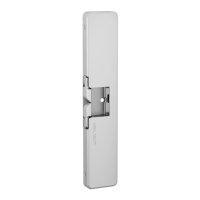
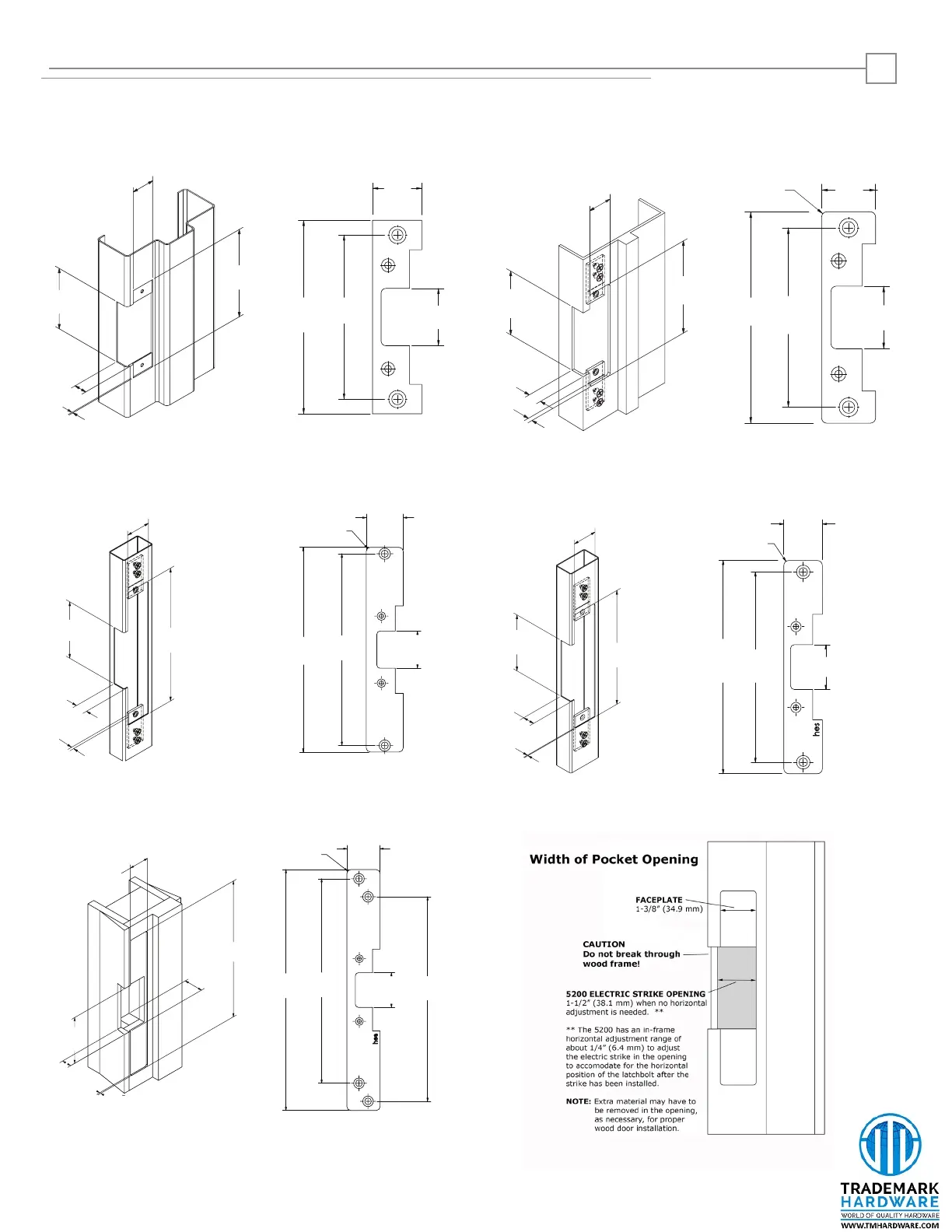
501 Faceplate Option (4-7/8” x 1-1/4”), Square Corners and Flat Faceplate
Used with cylindrical locksets in ANSI metal jambs
[mm]
501A Faceplate Option (4-7/8” x 1-1/4”), Radius Corners and Flat Faceplate
Used with cylindrical locksets or spring latches in aluminum frames
Inches
1 -1/4"
[31.8]
4 -7/8"
[124]
3 -3/8"
[85.7]
13/16"
[20.6]
3/32"
[2.3]
4 -7/8"
[124]
4 -1/8"
[104.8]
1 -7/16"
[36.6]
1 -1/4"
[31.8]
R 1/8"
[3]
3 -3/8"
[85.7]
1 -1/4"
[31.8]
4 -7/8"
[124]
13/16"
[20.6]
[2.3]
3/32"
[mm]
Inches
1 -1/4"
[31.8]
4 -7/8"
[124]
4 -1/8"
[104.8]
1 -7/16"
[36.6]
[mm]
Inches
3-3/8"
[85.7]
13/16"
[20.6]
3/32"
[2.3]
1 -7/16"
[36.5]
7-15/16"
[201.6]
1 -7/16"
[36.6]
7 -15/16"
[201.6]
7 -7/16"
[189]
1 -7/16"
[36.6]
R 3/16"
[4.1]
502 Faceplate Option (7-5/16” x 1-7/16”), Radius Corners and Flat Faceplate
Used with cylindrical locksets or spring latches in aluminum frames
[mm]
Inches
1 -1/4"
[36.5]
3 -3/8"
[85.7]
6 -7/8"
[174.3]
13/16"
[20.6]
3/32"
[2.3]
6 -7/8"
[174.3]
6 -1/8"
[155.6]
1 -1/4"
[31.8]
1 -7/16"
[36.6]
R 3/16"
[4.1]
503 Faceplate Option (6-7/8” x 1-1/4”), Radius Corners and Flat Faceplate
Used with cylindrical locksets or spring latches in aluminum frames
[mm]
Inches
10"
[254]
1 -3/8"
[34.9]
3 -3/8"
[85.7]
13/16"
[20.6]
3/32"
[2.3]
1 -3/8"
[34.9]
10"
[254]
8 -1/2"
[215.6]
8 -1/2"
[215.6]
1 -7/16"
[36.6]
1 -3/8"
[34.9]
R 1/8"
[4]
504 Faceplate Option (10” x 1-3/8”), Radius Corners and Flat Faceplate
Used with cylindrical locksets; four-point mounting for wood installations
Cutout Templates for Frame Preparation
NOTE: The 5200 has an in-frame horizontal adjustment range of about 1/4” (6.4 mm) to allow adjustment of the electric strike in the frame
opening to accomodate for the horizontal position of the latchbolt after the strike has been installed. The “Adjusting the Horizontal”
section provides steps for this adjustment.
 Loading...