EasyManua.ls Logo

Assa Abloy HES 8000 Series User Manual

Assa Abloy HES 8000 Series
6 pages
To Next Page IconTo Next Page
Page #1 background imageLoading...
Page #1 background image
8000/8300 Series Electric Strike
Installation Instructions
HES, Inc.
22630 N. 17th Ave.
Phoenix, AZ 85027
800-626-7590
www.hesinnovations.com
1
Product Components
Diagram 1: Electrical Specifications
ELECTRICAL RATINGS FOR SOLENOID
MINIMUM WIRE GAUGE REQUIREMENTS SOLENOID VOLTAGE
CONTINUOUS DUTY
12VDC
12VDC
50
.24
24VDC
24VDC
200 50 200
.12 .12
12-16VAC 24VAC
INTERMITTENT DUTY*
Resistance in Ohms
Amps
Solenoids are rated at +/- 10% indicated value.
*10% max duty cycle (2 min. max on time)
200 feet or less
200 - 300 feet
300 - 400 feet
18 gauge
16 gauge
14 gauge
20 gauge
18 gauge
16 gauge
12 & 24 Volt Pigtails
1
2
8000/8300 Electric Strike Body
Sticky Shims (optional use)
1
2
3
3
.24-.32

Other manuals for Assa Abloy HES 8000 Series

Question and Answer IconNeed help?

Do you have a question about the Assa Abloy HES 8000 Series and is the answer not in the manual?

Assa Abloy HES 8000 Series Specifications

General IconGeneral
Voltage12/24VDC
Endurance1, 000, 000 cycles
Strike Body MaterialStainless Steel
Fire RatingUL 10C, 3-hour fire rated
FinishSatin Stainless

Summary

Product Components

Installation Directions

Evaluate Opening

Verify the door opening is plumb and square before proceeding with installation.

Prepare Strike

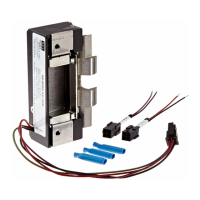
Select the correct plug-in connector and electrically connect the strike unit.

Prepare Frame

Prepare the door jamb according to the template details and install mounting tabs.

Finish Installing

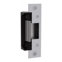
Install the strike unit, connect wires, and verify deadlatch clearance.

Installation Diagrams

Fail Safe to Fail Secure Conversion

Instructions for converting the electric strike between fail-safe and fail-secure modes.

Latchbolt Monitor Wiring

Details on wiring connections for the Latchbolt Monitor (LBM) feature.

Faceplate Installation

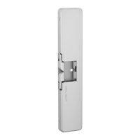
Illustrates the correct procedure for attaching the faceplate to the electric strike.

Vertical Alignment

Diagram showing the correct vertical alignment of the electric strike in the jamb.

Vertical Adjustability

Diagram illustrating how to adjust the electric strike for vertical positioning.

Cutout Templates

8000/8300 with 801 Faceplate Template

Provides dimensions for cutout and installation of the 8000/8300 strike with 801 faceplate.

Wire Drilling Diagram

Diagram showing recommended placement and size for drilling wire access holes.

Additional Cutout Templates

8000/8300 with 801A Faceplate Template

Dimensions for cutout and installation with 801A radius corner faceplate.

8000/8300 with 802 Faceplate Template

Dimensions for cutout and installation with 802 radius corner faceplate.

Further Cutout Templates

8000/8300 with 803 Faceplate Template

Dimensions for cutout and installation with 803 radius corner faceplate.

8000/8300 with 805 Faceplate Template

Dimensions for cutout and installation with 805 radius corner faceplate.

Related product manuals