Do you have a question about the Assa Abloy Harmony H1 and is the answer not in the manual?
Instructions for verifying door hand/bevel and preparing door holes according to template.
Procedure for reversing the lock body hand and the latch hand for proper installation.
Guide to setting the 3-position DIP switches on the mortise lock body before installation.
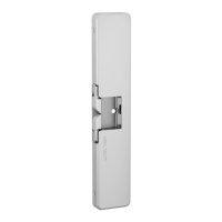
Steps for inserting and securing the mortise lock body into the door preparation.
Attaching the outside escutcheon and mounting plate to the door using specified screws.
Feeding the reader cable and securing the mounting plate to the outside escutcheon.
Instructions for installing the inside gasket, especially for outdoor applications.
Connecting the green/yellow ground wire ring terminal to the top right screw.
Steps for correctly orienting, inserting, and securing the cylinder into the escutcheon.
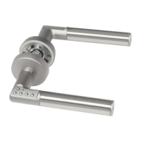
Installing the outside lever and inside adapter plate assembly onto the spindle.
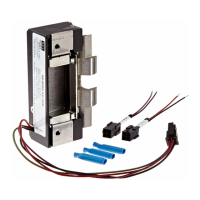
Connecting the ElectroLynx harness and PCB assembly according to wire assignments.
Steps to position ElectroLynx connectors and fold wires to prevent pinching during installation.
Securing the inside escutcheon to the mounting plate and checking functionality.
Installing the inside rose and lever, ensuring smooth operation of latch and deadbolt.
Attaching the front plate using specified screws and tightening securely.
Explanation of the three modes for configuring the reader's LED operation.
Application diagram for Mode 1 LED configuration showing wiring for a 12/24VDC system.
Application diagram for Mode 2 LED configuration showing wiring for a 12/24VDC system.
Application diagram for Mode 3 LED configuration showing wiring for a 12/24VDC system.
List of components and standards required for UL 294 certification.
| Brand | Assa Abloy |
|---|---|
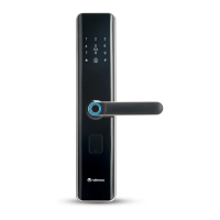
| Model | Harmony H1 |
| Category | Door locks |
| Language | English |