Copyright © 2015, Sargent Manufacturing Company, an ASSA ABLOY Group company. All rights reserved.
Reproductions in whole or in part without express written permission of Sargent Manufacturing Company is prohibited.
05/15/15
Harmony Series H1 Mortise Lock
A7877F • 800-810-WIRE (9473) • www.sargentlock.com
14
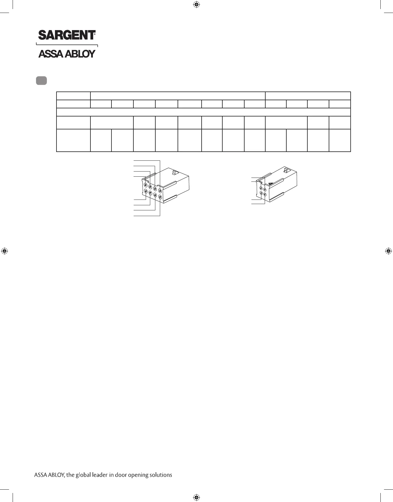
Product 8 PIN CONNECTION 4 PIN CONNECTOR
1-Black 2-Red 3-White 4-Green 5-Orange 6-Blue 7-Brown 8-Yellow 1-Violet 2-Gray 3-Pink 4-Tan
ACCESS CONTROL DEVICES: Harmony H1 Mortise, ElectroLynx wire Color / Function assignments
12VDC
Reader Power
WIE-
GAND
WIE-
GAND
RX (NO/
NC)
RX
(COM)
EGND LED 12 OR 24 VDC
(LOCK RELAY
DPS
(NC)
DPS
(COM)
SARGENT -
HARMONY
SERIES,
H1 Mortise
NEG POS DATA_1 DATA_0 REF.
STEP 2A
REF.
STEP
2A
REF.
DIA-
GRAMS
REF.
DIA-
GRAMS
NEG POS DPS DPS
Reader LED Configuration
The Harmony Series reader can be configured for (3) modes of LED operation:
Mode 1:
• Red LED ‘ON’ when powered.
• Presenting a 125kHz proximity card will cause LED to ‘FLICKER’ Green and return to Red state.
• Reference Diagram #1.
Note: LED wire is unconnected.
Mode 2:
• Green LED “ON” when powered.
• (No Flicker) after presenting valid 125kHz proximity card.
• Reference Diagram #2.
Note: LED wire must be connected to circuit GROUND of the system’s power supply.
Mode 3:
• EAC Panel controls LED operation.
• Reference Diagram #3.
Note: Control of LED is a function of the EAC panel equipment (ie. Relay) to toggle between Green & Red.
Note: When LED wire is tied directly into EAC panel relay, no AC signals should be applied on wire or
door reader performance will be impacted (Ref. Diagram #3).
PIN8 (Yellow – LED)
PIN 6 (Blue – RX)
PIN 4 (Green – Data 0)
PIN 2 (Red – Reader POS)
PIN 1 (Black – Reader NEG)
PIN 3 (White – Data 1)
PIN 5 (Orange – RX)
PIN 7 (Brown)
PIN 4 (Tan – DPS)
PIN 2 (Gray – Lock POS)
PIN 1 (Violet – Lock NEG)
PIN 3 (Pink – DPS)
Wiring Diagrams
7
If your lock is configured with End of Line Resistors, reference instruction sheet A8191 for the wiring of
RX & DPS outputs.
 Loading...