Copyright © 2015, Sargent Manufacturing Company, an ASSA ABLOY Group company. All rights reserved.
Reproductions in whole or in part without express written permission of Sargent Manufacturing Company is prohibited.
05/15/15
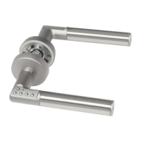
Harmony Series H1 Mortise Lock
A7877F • 800-810-WIRE (9473) • www.sargentlock.com
10
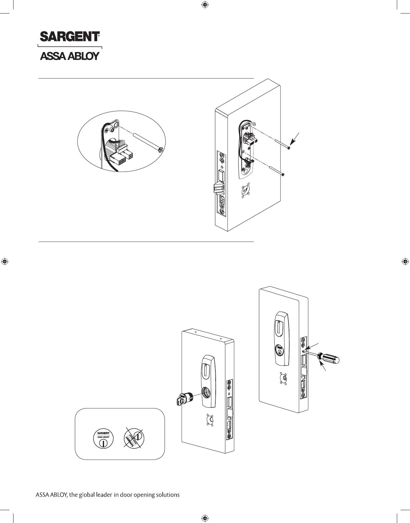
Connect pin 5 green/yellow ground wire ring terminal
to top right screw.
Fig. 7B Detail
Fig. 7A
(2) #8-32 x 2”
Phillips Flat Head
Machine Screw
Fig. 8B
1. Verify orientation of cylinder so that SARGENT logo is right-side up (Fig. 8A).
2. Withdraw the key about 25% out of the cylinder before inserting into the escutcheon (Fig. 8B).
3. Use the key to rotate the cylinder clockwise until it is flush at the bottom and the SARGENT
logo is right-side up.
Do not attempt to tighten all the way.
4. Tighten the cylinder clamp set screw to prevent
unscrewing of the cylinder (Fig. 8C).
5. Test cylinder function:
• 70/71 Function: Key retracts latch.
• 80/81 Function: Key retracts latch
and projects and retracts deadbolt.
• Ensure smooth operation of
latchbolt and deadbolt.
NOTE: Use lever holes
to manipulate mortise to ease
thread engagement of cylinder.
Fig. 8C
Cylinder Set Screw
Phillips
Screwdriver
Outside of Door
IMPORTANT: Position cylinder so that the
SARGENT logo is right-side up.
Correct Incorrect
Fig. 8A
7 Connect Earth Ground
8 Outside Cylinder Installation
 Loading...