Standard Applications
Optional Applications
Pull Side Door Mount
Right Hand Door - RH
Left Hand Reverse - LHR
Left Hand Door - LH
Right Hand Reverse - RHR
Pull Side Frame Mount
422D Back Plate required if frame face is less than 3" (76mm).
Right Hand Door - RH
Left Hand Reverse - LHR
Left Hand Door - LH
Right Hand Reverse - RHR
Right Hand Door - RH
Left Hand Reverse - LHR
Left Hand Door - LH
Right Hand Reverse - RHR
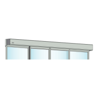
Push Side Door Mount
63-0853 Angle Bracket required.
Hinge Side
of Door
Hinge Side
of Door
Right Hand Door - RH
Left Hand Reverse - LHR
Left Hand Door - LH
Right Hand Reverse - RHR
Push Side Frame Mount
Hinge Side
of Door
Hinge Side
of Door
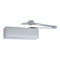
Included Components
Closer Body
Screw Pack
Closer Body
Optional Components
422D Back Plate
(required for pull side frame
mounted applications)
Power
Adjustment
Shaft
Slide Track
Assembly
Spring Stop
Full Cover
with Insert
60-0853
Slide Track
Angle Bracket
(required for push
side door mounted
applications)
Hold Open Device
(Standard with Hold
Open model)
Slide Track
Arm
Track Mounting
Screw Pack
Spline Shaft
Screw Pack
1-800-727-5477 • www.sargentlock.com
A8386 03/24 Rev 3
63-8386-6000-999
Installation Instructions
422 Cam Action Door Closer
Push and Pull Side, Door and Frame Mounted
Non-Hold Open and Hold Open Applications
Copyright © 2023, 2024, SARGENT Manufacturing Company. All rights reserved. Reproduction in whole or in part without the express
written permission ofSARGENT Manufacturing Company is prohibited. Patent pending and/or patent www.assaabloydss.com/patents.
CAUTION
An incorrectly installed or improperly adjusted door closer can cause
property damage or personal injury. These instructions should be
followed to avoid the possibility of misapplication or misadjustment.
Hold open units are not permitted to be installed in fire door assemblies.
NOTES:
‒ For special applications a separate door and frame preparation tem-
plate is packed with these instructions.
‒ Use this instruction sheet for installation sequence and closer adjust-
ments only.
‒ Use of an auxiliary door stop is always recommended.
READ AND FOLLOW ALL INSTRUCTIONS.
SAVE THESE INSTRUCTIONS.
The closing force for Series 422 door closers is adjustable
from a size 1 to a size 6, as outlined in ANSI Standard A156.4.
When these series of door closers are installed and adjusted
to conform to ADA reduced opening force requirements
(5 lbs max.) for interior doors, they may not have adequate
closing force to reliably close and latch the door. Power
adjustments charted on page 2 are recommended
where possible, to ensure proper door control.
Approved 2024-03-15