V2.4 03/08/18 TD0068 Page 22 of 38
This Document is uncontrolled when printed unless over stamped “CONTROLLED DOCUMENT”
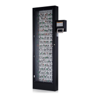
6.5 FIXING TO THE WALL
NOTE: Traka Systems can be heavy. The Touch system must be secured to the wall, as described in this
section, to eliminate risk of injury or damage. The system may also require two persons to lift it.
1. Locate the desired position on the wall you wish the Touch system and any extension cabinets (if applicable) to
go. The main cabinet should be no further than 1 Meter from the mains spur.
2. Stand the system in place and mark the wall at all 6 fixing holes in the cabinet and both fixing holes in the
Pod.
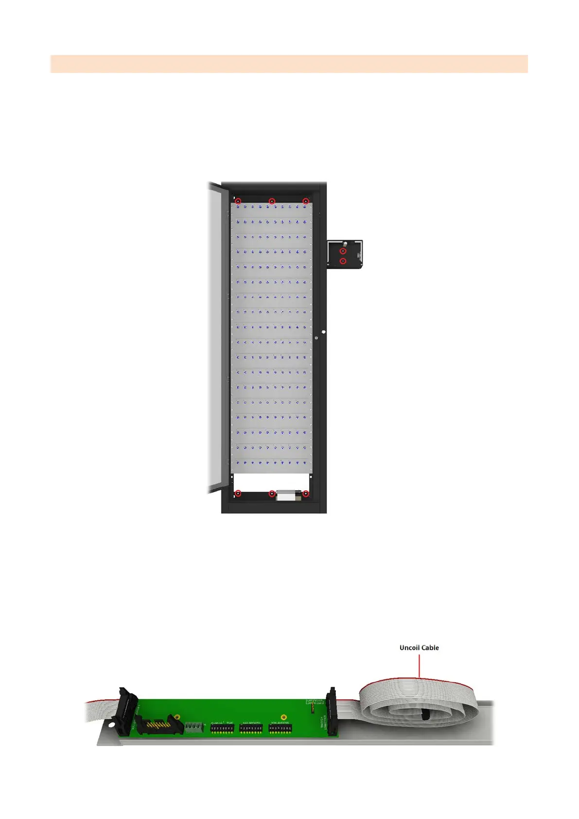
3. If the cabinet is part of a system with extension cabinets you will need to prepare the interface cable before
securing the system to the wall. If this is not an extension system, continue to step 6.
NOTE: If you are adding an extension cabinet to an existing system, an Interface PCB and chassis
will have been supplied for the existing cabinet and must be fitted behind the blank fascia at the
top of the cabinet, replacing the existing strengthener.
4. If not already connected, connect the Receptor Cable and Door Lock Cable to the Interface PCB of the main
cabinet and uncoil the receptor cable as shown below.
 Loading...