V2.4 03/08/18 TD0068 Page 9 of 38
This Document is uncontrolled when printed unless over stamped “CONTROLLED DOCUMENT”
1. Primary CANbus – through-connection connects to the Traka Touch PCB (if it is in the main cabinet) or
the previous cabinet (if it is in an extension system).
2. Secondary CANbus - connects to the receptor strips in the local cabinet.
3. Cabinet Door Solenoid and Switch - connects to the door lock mechanism in the local cabinet.
4. Cabinet Address - (0=Off, 1=On) 0000 = Cabinet 1, 1000 = Cabinet 2, 0100 = Cabinet 3, 1100 =
Cabinet 4.
5. Max Receptor Address - must be set to match the bottom (highest address) receptor strip in the local
cabinet.
6. Min Receptor Address - must be set to match the top (lowest address) receptor strip in the local
cabinet
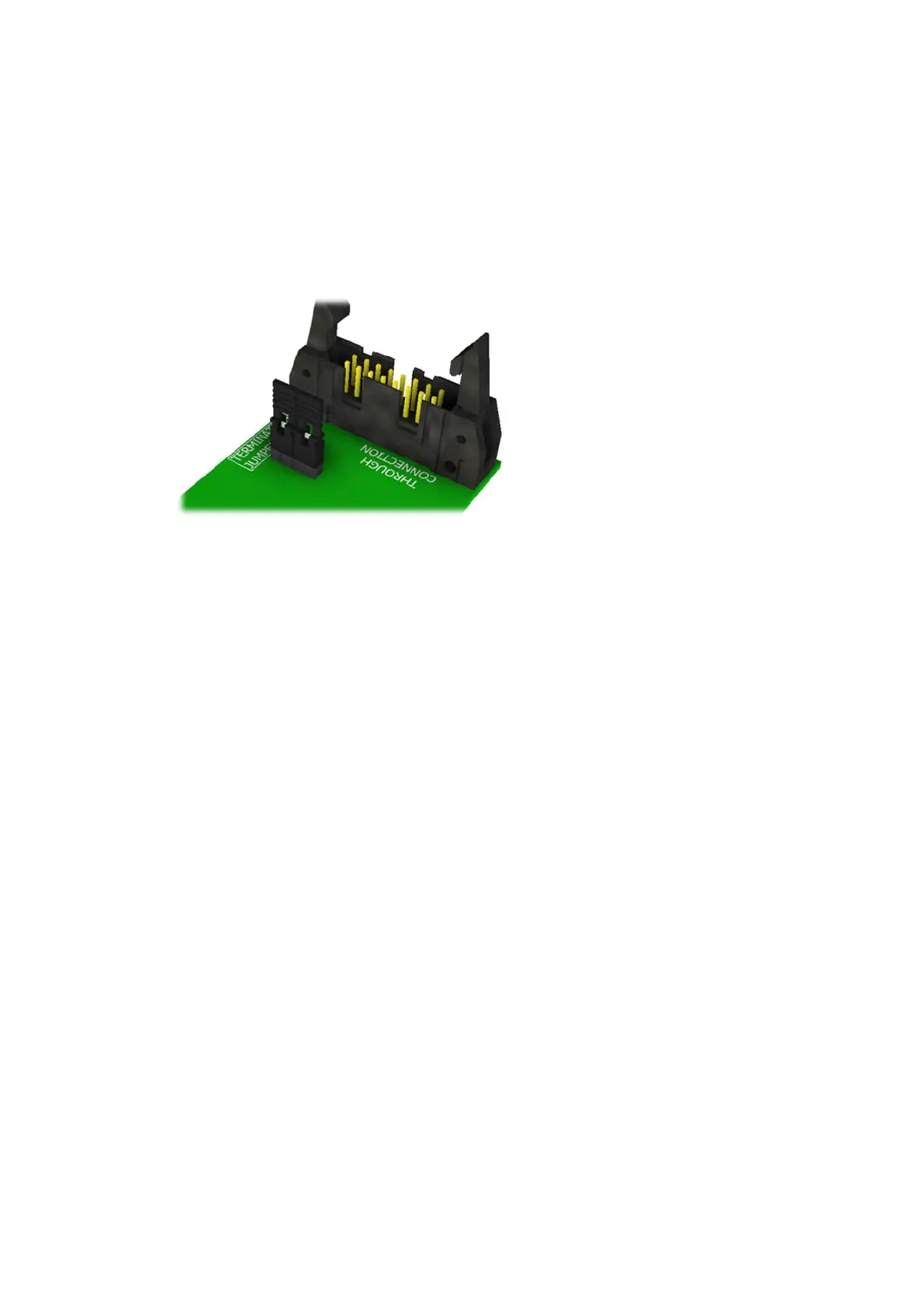
7. Termination Jumper Links - must be fitted here on the last cabinet in the chain only as show below.
8. Primary CANbus - through-connection connects to the next extension cabinet in the chain.
 Loading...