23
q Connect the RED wires to the pads labeled LB+1 and B+1 on the
flanking L & R Filter Bank PC boards. Repeat the process to connect
the Black wires to the LCOM and RCOM from the common c l u s t e r
pads ‘L’ and ‘R’.
Wiring to the Main PCB:
At this point, for soldering purposes, you may find it convenient to
place all the PCB’s upside down to make the upcoming connections.
q Main PCB x 1
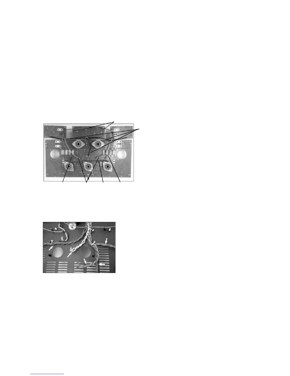
q Using the photo below as a guide, connect the Black wire from the
Main Filter Bank common cluster to the center pad labeled ‘Com’
between the ‘L’ and ‘R’ pads. These pads are located near the center
of the Main PCB.
q Connect the LB+2 and B+2 BROWN wires from the Left and Right
Filter Banks to the corresponding pads on the Main PCB.
q Connect the LB+3 and B+3 BLUE wires from the Left and Right
Filter Banks to the corresponding pads on the Main PCB.
q The result needs to look like this photo.
Power Transformer Wire Routing:
The power transformer has 6 sets of secondary windings, 5 Filament
windings and the source of all the high voltages needed in this 300B
amplifier design are derived from a single center-tapped high voltage
winding. Most of these wires, all but the RED group, will be ro u t e d
u n d e rneath the circuit boards and there f o re soldered from the top of
the circuit boards.
q To accomplish this layout it is best to copy what is shown in the
photos above. Sorry for the lack of descriptions but as they say, ‘a
p i c t u re is worth a thousand words’, and besides, I don’t feel like typing
those thousand words.
q Since the wires are already cut to length, simply form the leads and
tie them off to the chassis standoff’s with the wire ties in the indicated
positions and then with my guidance, we will mount the PCB’s. CUE:
D o n ’t over-tighten the wire ties, it is not necessary and if you do, you
may run the risk of shorting the wire s .
q It looks like you are doing a fine job. Once you have the wires in
place, test the placement of the Main PCB by positioning it into the
chassis exactly where it is to be mounted. The tube sockets need to
settle down into position in the chassis without interf e rence from any
of the wires below it.
Mounting the PCB’s into the Chassis:
Yes we are getting very close now to filling the chassis and fulfilling
your dream of building your very own single ended 300B amplifier.
The Choke, O/P transformers and Power transformer will all be
connected to their PCB’s in this sequence of the construction pro c e s s .
#6-32 S/S Philips x 20
#6 Internal Tooth Lock Washers x 2
q Place the set of PCB’s right side up above where they will be mounted.
q Tilt the Main Filter Bank towards the Main PCB so that you may gain
access to the pads for mounting the Choke leads from undern e a t h .
q F rom the bottom, insert the CHOKE leads into the pads labeled
‘CH’. Solder from the top and trim the leads.
q Locate the Blue wires from the O/P transformers and plug them into
the rear side of the Main Filter Bank board into their respective pads
labeled ‘RO/P’ and ‘LO/P’. Again soldering from the top and trimming
the leads.
Now is a good time to connect the RED H.V. wires and RED / YELLOW
center tap wire .
q F rom the top of these boards, install the Yellow striped Red wire into
the pad labeled ‘CT’ on the Main Filter Bank PCB, and the Red wire s
into the pads labeled ‘RED’ on the Main PCB.
This is where you may need someone to help hold up the Main PCB
while you make the underside connections. Someone else’s aid may
not be necessary, but why not share some of your inevitable
c o n s t ruction success and glory? In any case, you will be connecting
the rest of the interconnecting wires from the power transform e r
s e c o n d a ry windings.
q While lifting the Main PCB so that you view its under side from the
f ront. Locate the following wires and pad locations and install them in
the following ord e r.
1 - Ye l l o w, 2 - Gray, 3 - Blue, 4 - Violet, 5 - Gre e n .
CUE: Look for the text on the bottom of the PCB to help identify the
c o rrect wire locations.
q Be sure to always solder from the top of the PCB and to trim the
excess leads when done.
q I trust that all went well. Settle all four PCB’s down and onto their
s t a n d o ff’s. Be sure that there are no wires wedged between any PCB
and standoff or between any tube socket and the chassis. The board s
will settle into place easily if all is clear.
q Using the #6 screws secure all the PCB’s into position. Note that two
#6 lock washers are used where indicated on the PCB above and
below the V2 socket.
A re you saying that it looks like I forgot something? Well I hope not,
but maybe your keen eye has picked out the mystery location of one
of the few remaining parts of this electronic jigsaw puzzle. There is a
5W resistor that must be mounted - it will straddle both the Main Filter
Bank PCB and the Main PCB.
q R(no name) 6R8 5Watt Bridges Main PCB and Main Filter Bank
q Find the 6R8 resistor and solder it into position. CUE: Raise the
resistor above the PCB and keep the lead lengths short enough not to
extend too far below the surface of the board. You can not trim them
f rom here .
q Connect the BLACK speaker post wires to the main PCB in locations
RC and LC for left and right channels.
G reat work again. You might be saying by now, “Gee it is starting to
look like I am done!” Well not quite, but close.
300B Socket Connections:
Next we will connect the 300B tube socket pins to the Main PCB. This
is where we use some of the heavy gauge lead clippings from the
bl u e
ye l l o w
v i o l e t
g r e e n
g r a y
RED
BLK
BLU
BRNBRN
GRN
 Loading...