This document is an operation and service manual for the Associated Research, Inc. Models 7550DT and 7564SA Electrical Safety Compliance Analyzers. These instruments are designed to perform various electrical safety compliance tests.
Function Description
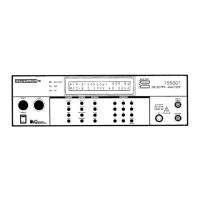
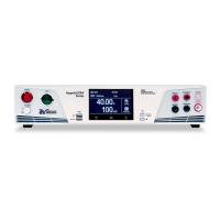
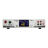
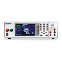
The HypotULTRA II (Model 7550DT) and QUADCHEK II (Model 7564SA) combine multiple dielectric safety tests into a single 19-inch rack-mount cabinet.
Model 7550DT HypotULTRA II performs:
- AC Hipot with Insulation Resistance Test
- DC Hipot with Insulation Resistance Test
- Continuity Test
Model 7564SA QUADCHEK II performs:
- AC Hipot with Insulation Resistance Test
- DC Hipot with Insulation Resistance Test
- Ground Bond Test
Both models include either an IEEE-488 (GPIB) or RS-232 interface as standard features, allowing for automated production environments.
Important Technical Specifications
General Specifications (Models 7550DT / 7564SA):
- Input Voltage: 115/230 VAC ± 15%, Single Phase, User selection
- Frequency: 47 - 63 Hz
- Fuse: 6.3 Amp 250V Slo-Blo
- Memory: Stores up to 50 groups of different test programs, with 8 steps per memory.
- Security: Programmable password lockout.
- LCD Contrast Setting: 9 ranges.
- Buzzer Volume Setting: 10 ranges.
- Calibration: Software and adjustments via front panel.
- Mechanical: Bench or rack mount with tilt-up front feet.
- Dimensions (WxHxD): 17 x 5.8 x 20.3 in. (432 x 147 x 515 mm)
- Weight:
- 7564SA without scanner: 52.5 lbs (24 Kgs)
- 7564SA with built-in scanner: 57 lbs (26 Kgs)
- 7550DT without scanner: 50.5 lbs (23 Kgs)
- 7550DT with built-in scanner: 55 lbs (25 Kgs)
- Scanner Port: Two Port Maximum, including built-in scanner.
- Built-in Scanner Option: High Voltage x 8 Ports (7564SA and 7550DT), Ground Bond x 8 Ports (7564SA only).
- Real Current Option: Measuring Range: 0-3500µA (resolution & accuracy same as total current measuring).
Dielectric Withstand Test Mode (ACW / DCW):
- Output Rating: 5 KV @ 40 mA AC, 6 KV @ 10 mA DC
- Output Adjustment Range: 0 - 5 KV AC, 0 - 6 KV DC
- Voltage Resolution: 1 volt/step
- Voltage Accuracy: ± (2% of setting + 5 volts)
- Ramp-HI: 12mA peak maximum, ON/OFF selectable.
- Charge-LO Range: 0.0 - 350.0µA DC or Auto set.
- HI-Limit AC Range: 0.00 - 40.00 mA (Resolution: 0.01 mA/step, Accuracy: ± (2% of setting + 2 counts))
- HI-Limit DC Range: 0 - 3500µA (Resolution: 1µA/step, Accuracy: ± (2% of setting + 2 counts))
- LO-Limit AC Range: 0.000 - 9.999 mA (Resolution: 0.001 mA/step, Accuracy: ± (2% of setting + 2 counts))
- LO-Limit DC Range: 0.0 - 999.9 µA (Resolution: 0.1 µA/step, Accuracy: ± (2% of setting + 2 counts))
- Arc Detection Range: 1 - 9
- Failure Detector: Audible and Visual
- Voltage Display Range: 0.00 - 6.00 KV Full Scale (Resolution: 10 volt/step, Accuracy: ± (2% of reading + 2 counts))
- Current Display Auto Range:
- AC: 0.000 - 3.500mA (Resolution: 0.001mA/step, Accuracy: ± (2% of reading + 2 counts))
- AC: 3.00 mA - 40.00 mA (Resolution: 0.01 mA/step, Accuracy: ± (2% of setting + 2 counts))
- DC: 0.0 µA - 350.0 µA (Resolution: 0.1 µA/step, Accuracy: ± (2% of reading + 2 counts))
- DC: 300 µA - 3500 µA (Resolution: 1 µA/step, Accuracy: ± (2% of reading + 2 counts))
- DC Output Ripple: < 4% Ripple RMS at 6 KV DC @ 3.5 mA, Resistive Load
- AC Output Wave Form: Sine Wave, Crest Factor = 1.3 - 1.5
- Output Frequency: 60 or 50 Hz, User Selection (Accuracy: ±100 PPM)
- Output Regulation: ± (1 % of setting ± 5 volts) from no load to full load
- Dwell Timer Range: 0, 0.3 - 999.9 sec (0 = Constant) (Resolution: 0.1 sec increments, Accuracy: ± (0.1% ± 0.05 sec))
- Ramp Timer Range: AC 0.1 - 999.9 sec, DC 0.4 - 999.9 sec (Resolution: 0.1 sec increments, Accuracy: ± (0.1% + 0.05 sec))
Insulation Resistance Test Mode:
- Output Voltage Range: 100 - 1000 Volts DC (Resolution: 1 volt/step, Accuracy: ± (2% of reading + 2 volts))
- Short Circuit Current Maximum: 12mA peak
- Voltage Display Range: 0 - 1000 V (Resolution: 1 volt/step, Accuracy: ± (2% of reading + 2 counts))
- Resistance Display Range: 1 - 9999 MΩ (4 Digit, Auto Ranging)
- Resolutions vary by voltage (500VDC, 1000VDC) and MΩ range (e.g., 0.001 MΩ to 1 MΩ).
- Accuracy: ± (2% of reading + 2 counts) at test voltage 500 - 1000V and 1 - 1000 MΩ.
- Accuracy: ± (8% of reading + 2 counts) at test voltage 500 - 1000V and 1000 - 9999 MΩ.
- Accuracy: ± (8% of reading + 2 counts) at test voltage 100 - 500V and 0 - 1000 MΩ.
- Charge-LO Range: 0.000 - 3.500µA or Auto Set.
- HI-Limit Range: 0 - 9999 MΩ (0 = Off).
- LO-Limit Range: 1 - 9999 MΩ.
- Delay Timer Range: 0, 0.5 - 999.9 sec (0 = Constant) (Resolution: 0.1 sec/step, Accuracy: ± (0.1% + 0.05 sec)).
Ground Bond Test Mode (Model 7564SA only):
- Output Voltage (Open Circuit Limit) Range: 3.00 - 8.00 Volts AC (Resolution: 0.01 volt/step, Accuracy: ± (2 % of Setting + 0.03V) O.C. Condition)
- Output Frequency: 60 or 50 Hz, User Selection (Accuracy: ±100 PPM)
- Output Current Range: 3.00 - 30.00 Amps AC (Resolution: 0.01 Amp/step, Accuracy: ± (2 % of Setting + 0.02 A))
- Current Display Range: 0.00 - 30.00 Amps (Resolution: 0.01 Amp/step, Accuracy: ± (3 % of Reading + 0.03 A))
- Resistance Display Range: 0 - 600 mΩ (Resolution: 1 mΩ/step, Accuracy: ± (2 % of Reading + 2 mΩ))
- HI-Limit Range: 0 - 600 mΩ for 3 - 10 A, 0 - 150 mΩ for 3 - 30 A (Resolution: 1 mΩ/step, Accuracy: ± (2 % of Setting + 2 mΩ))
- LO-Limit Range: 0 - 600 mΩ for 3 - 10 A, 0 - 150 mΩ for 3 - 30 A (Resolution: 1 mΩ/step, Accuracy: ± (2 % of Setting ± 2 mΩ))
- Dwell Timer Range: 0, 0.5 - 999.9 sec (0 = Constant) (Resolution: 0.1 sec/step, Accuracy: ± (0.1% + 0.05 sec))
- Milliohm Offset Max. Offset Capability: 200 mΩ (Resolution: 1 mΩ / step, Accuracy: ± (2 % of Setting + 2 mΩ))
Ground Continuity (Model 7550DT only):
- Current: DC 0.1 A ± 0.01A, fixed
- Max. ground resistance: 1 Ω ± 0.1Ω, fixed
Usage Features
- Single 2 x 20 LCD Display: Provides clear indication of all test results and setup parameters, simplifying operation.
- Quick Access User Interface: Dedicated "hot keys" allow users to quickly navigate through instrument modes without extensive menu scrolling.
- Enhanced Storage Capability: Stores up to 50 test setups, each with up to 8 steps, which can be linked for a maximum of 400 sequential steps.
- Exclusive CHARGE-LO Function: Enhances DC Hipot testing by ensuring proper DUT connection, monitoring momentary charging current to detect connection issues. Includes an auto-setup mode.
- RAMP-HI Function: Allows for a higher trip rate during the ramp-up phase of DC Hipot tests, preventing false failures due to charging current and increasing throughput.
- Programmable Security Password System: Prevents unauthorized personnel from altering test parameters.
- High Resolution Current Metering: Improved resolution for AC Hipot (1 microamp) and DC Hipot (0.1 microamp).
- High Resolution Timers: Ramp and dwell time resolution improved to 0.1 second increments.
- Digitally Adjustable Arc Detection: Menu-controlled arc detection with sensitivity adjustable from 1-9, and programmable via remote interface.
- HypotULTRA II Continuity Mode (7550DT only): Added for basic low current ground continuity tests, complying with UL and other safety agency specifications.
- Fail Stop ON/OFF Mode: Useful in scanner applications, allowing the instrument to continue testing after a failure or stop. Displays all PASS/FAIL results at the end of the test cycle.
- Buffer Memory: Stores complete test results for up to 8 tests, allowing users to review results for each step.
- Enhanced GPIB Functions: Improved remote control with Service Request Interrupt (SRQ) capability for events like test failures, aborted tests, and command errors. Allows retrieval of stored test results and real-time data acquisition.
- Real Current Option (Optional): Allows monitoring only the real portion of leakage current, ignoring reactive components due to capacitance, which is crucial for detecting small increases in real leakage current that might otherwise be masked by reactive current.
- High Resolution IR Milliohm Meter (Optional): Provides lower resistance readings with improved resolution (0.1 kΩ from previous 1 MΩ), minimum reading of 50 kΩ, and maximum reduced to 99.99 MΩ.
- Grounded Return Option (Optional): Allows testing devices with chassis earth grounded, enabling monitoring of very low leakage currents by eliminating stray leakage current measurement errors.
- RS232 Interface (Optional): Can be substituted for the standard GPIB interface, offering all GPIB function control except SRQ functions.
- Dual Remote Test Switches (Optional): Configurable for safe production line operation, requiring two switches to be pressed within 0.5 seconds to activate a test. Disables front panel Test/Reset switches when enabled.
Maintenance Features
- User Service: To prevent electric shock, the instrument cover should not be removed. No user-serviceable parts inside. Routine maintenance or cleaning of internal parts is not necessary.
- External Cleaning: Use a clean dry or slightly damp cloth. Avoid cleaning agents or chemicals that could damage controls or plastic parts.
- Service Interval: The instrument, power cord, test leads, and accessories must be returned at least once a year to an Associated Research authorized service center for calibration and inspection of safety-related components.
- User Modifications: Unauthorized modifications void the warranty. Associated Research is not responsible for injuries from unauthorized modifications or non-specified parts.
- Packaging for Return: Retain original packaging. If returning for service, obtain an RMA number, enclose all options/accessories/test leads, indicate the problem, and mark the container "FRAGILE". If original packaging is unavailable, use a strong double-wall container (350 lb test material), wrap the instrument in bubble pack/foam, protect the control panel with cardboard, and seal securely.
- Fuse Replacement: Unplug the power cord, turn the fuse receptacle counter-clockwise to expose the compartment, and replace with a fuse of the proper rating.