Do you have a question about the Associated Research OMNIA II 8204 and is the answer not in the manual?
Details the manufacturer's warranty, including duration, extension, and service requirements.
Explains product marking and caution/warning symbols for safe operation and hazard awareness.
Defines technical terms used throughout the manual for clarity.
Provides essential safety precautions, user warnings, and handling instructions for the instrument.
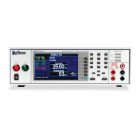
Highlights the main functionalities and benefits of the OMNIA II electrical safety analyzer.
Guides on safely unpacking and inspecting the instrument for damage upon arrival.
Details the requirements and steps for setting up the instrument, including work area and power.
Lists the technical specifications for the OMNIA II, covering various test modes and parameters.
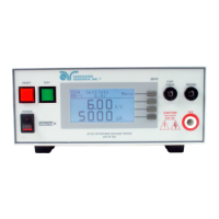
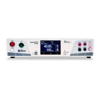
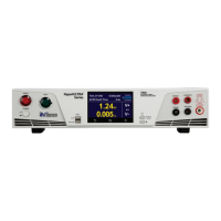
Describes the front and rear panel controls, buttons, and connectors for operating the instrument.
Explains the instrument's power-on sequence and the initial main menu display.
Details how to access and configure system settings like time, date, hardware, and security.
Guides on creating, editing, and managing test sequences, including adding, deleting, and saving tests.
Explains the various test parameters available and their default values for different test types.
Provides a step-by-step guide on creating and configuring test sequences for various test types.
Details how to connect test leads, adapter boxes, and other accessories to the instrument.
Explains how to load files, run tests step-by-step, manage fail stops, and view results.
Outlines the procedure for executing a selected test or a sequence of tests on the instrument.
Describes the metering screens displayed during tests and the information they provide.
Lists and explains the various test status and error messages displayed by the instrument.
Details the remote signal outputs for monitoring PASS, FAIL, and PROCESSING conditions.
Explains how to use remote connectors for TEST, RESET, INTERLOCK functions and memory selection.
Provides information on using and configuring the USB/RS-232 interface for remote control.
Lists and describes commands for controlling the instrument via USB, RS-232, and GPIB interfaces.
Details the optional GPIB interface for instrument control, including connectors and limitations.
Explains the interface functions that specify a device's capability to send, receive, and process messages.
Describes how to save, create, and delete files in non-volatile memory to manage test sequences.
Lists and describes the factory-installed options available for the instrument, with their corresponding codes.
Explains the FailCHEK process for verifying instrument failure detection circuitry.
Outlines the warranty terms and requirements for instrument recertification and extended warranty.
Details the hardware calibration procedure for specific ranges, required prior to software calibration.
Describes how to enter the instrument's calibration mode upon powering it ON.
Explains how to navigate and select individual calibration points for the instrument.
Lists calibration points and the associated loads, standards, and processes required for calibration.
Provides specifications for setting leakage current limits across various ranges and conditions.
Details the auto-ranging specifications for touch current display in AC+DC and AC only modes.
Specifies fixed range display parameters for touch current, including accuracy and error.
Lists auto-ranging specifications for touch voltage display in AC+DC and DC only modes.
Details fixed range display parameters for touch voltage, including accuracy and error.
| Brand | Associated Research |
|---|---|
| Model | OMNIA II 8204 |
| Category | Measuring Instruments |
| Language | English |