30
High Voltage Connections
The 25-pin control cable (p/n 38592) connects between the rear panel
SCANNER 1 or SCANNER 2 connector of OMNIA and the rear panel
SCANNER BUS INPUT connector of the SC6540.
The high voltage cable (p/n HS-8-12) is used to connect from the high
voltage rear output connector of OMNIA to the rear high voltage input of the
SC6540
The Ground Bond return cable (p/n 38556 for the 8100/8200) is used to
connect from the return rear connector OMNIA to the rear panel return
connection of the SC6540.
The red Ground Bond output cable (p/n 38555 for the 8100/8200) is used to
connect between the rear panel current output of OMNIA and the rear panel
current input of the SC6540.
The high voltage to banana style connection cable (p/n 38879) is used to
connect between the rear panel probe hi and probe lo terminals on the
8200 series and the rear panel current and return of the SC6540. NOTE:
these connections are utilized for the 8206, 8256, 8207 and 8257 only.
Eight high voltage connectors (p/n HS-8-13) are provided with a reel of
cable and assembly instructions so that each user can assemble the
lengths of the high voltage cable to meet their specific needs.
Under certain conditions high voltage can appear on the
cabinet of the SC6540. The ground terminal on the rear
panel of the SC6540 must be connected to a good earth
ground to ensure operator safety.
Ground Bond Connections
The rear panel of the SC6540 can include up to sixteen output terminals for
Ground Bond testing if this configuration is selected at the time of purchase.
We recommend using standard 12 gauge wire for operation at 30 amps and
10 gauge wire for 40 amps.
The wires should be attached using the hook-style crimp lugs provided, to
minimize connection resistance. The Kelvin connection of an Associated
Research ground bond tester will end at the ground bond input terminals of the
SC6540 scanner. For this reason, the wire lengths going from the SC6540 high
current outputs and the high current return should be kept as short as possible to
limit the effect of test lead resistance.
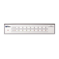
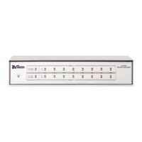
4.3.2. Connection Diagrams
 Loading...