PHOENIX Talon - Operation and Service Manual
14
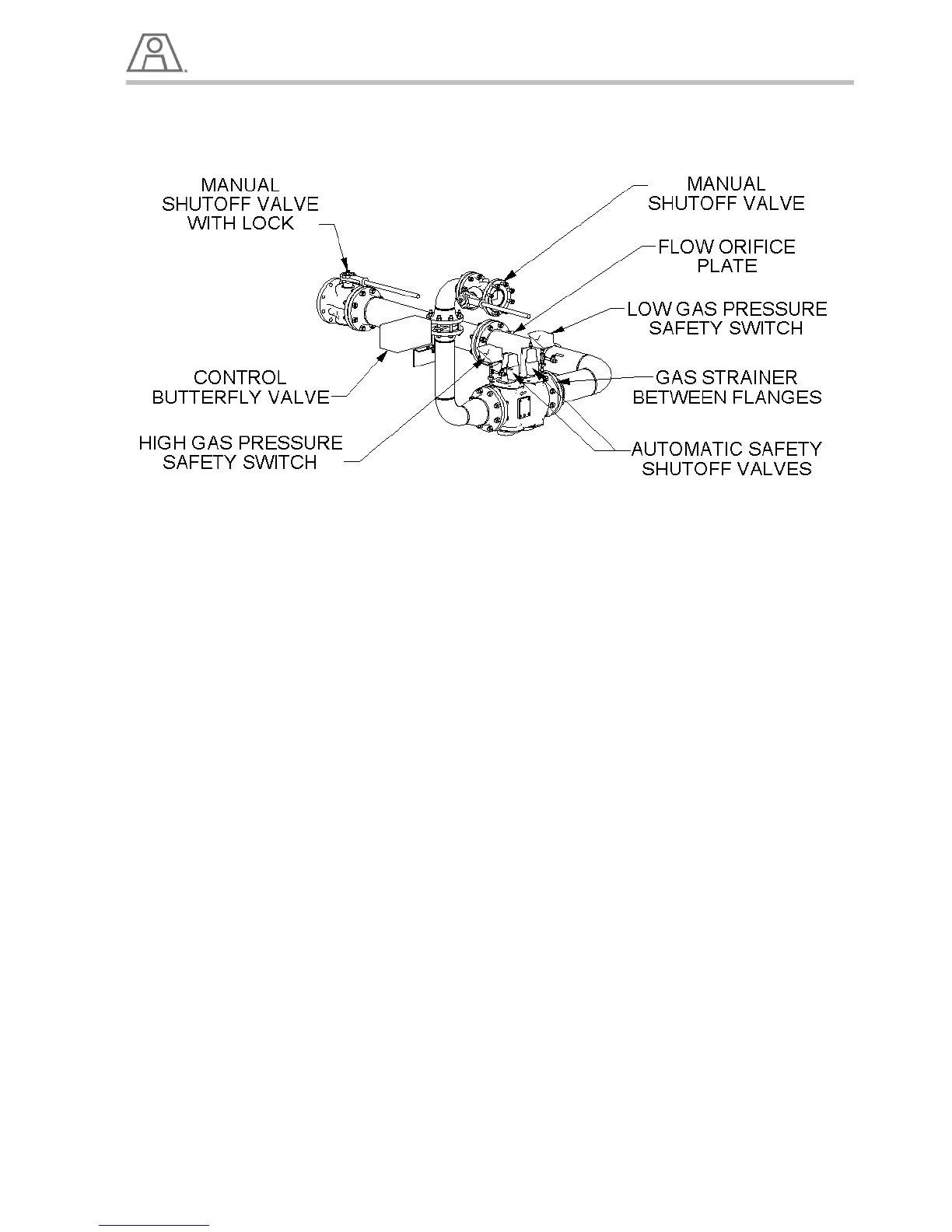
Natural Gas Fuel Piping System
Illustration 6 - Gas Train Components
1. Install a controlling gas regulator in the main gas line within 25 feet of the burner.
a. This regulator should be sized to provide the required gas flow at the inlet of the burner manifold.
b. See Table 5 for the nominal expected gas pressure required at the burner.
c. Exact gas pressure must be set at the initial start-up depending on piping configuration, burner
size, and maximum capacity desired.
2. The piping from the gas regulator outlet to the burner gas manifold should be sized to minimize
pressure losses.
3. The pipe size from the control regulator to the gas train, can be identical to the gas pipe size at the
entrance to the burner gas train, see tables below.
NOTE:
It is normal for the regulator size to be smaller than the line size.