PHOENIX Talon - Operation and Service Manual
25
Flame Shape Adjustments
1. The PHOENIX TALON Burner is preset at the factory for the shortest and narrowest flame possible.
This makes flame adjustment burners virtually obsolete.
2. The nose spin vanes affect the flame shape and combustion intensity.
3. Do not change the spin vanes from the factory settings. (They are preset at 45 to 60.)
4. The length of the flame must be shorter than the combustion zone in your drum. (Material that
showers through the flame causes increased pollutants in the flue gas.)
5. The width of the flame must be less than the I.D. of the combustion flights.
6. See the detailed Burner Performance Data Sheets for the flame size and diameter. (See Burner
Performance Data Sheets.)
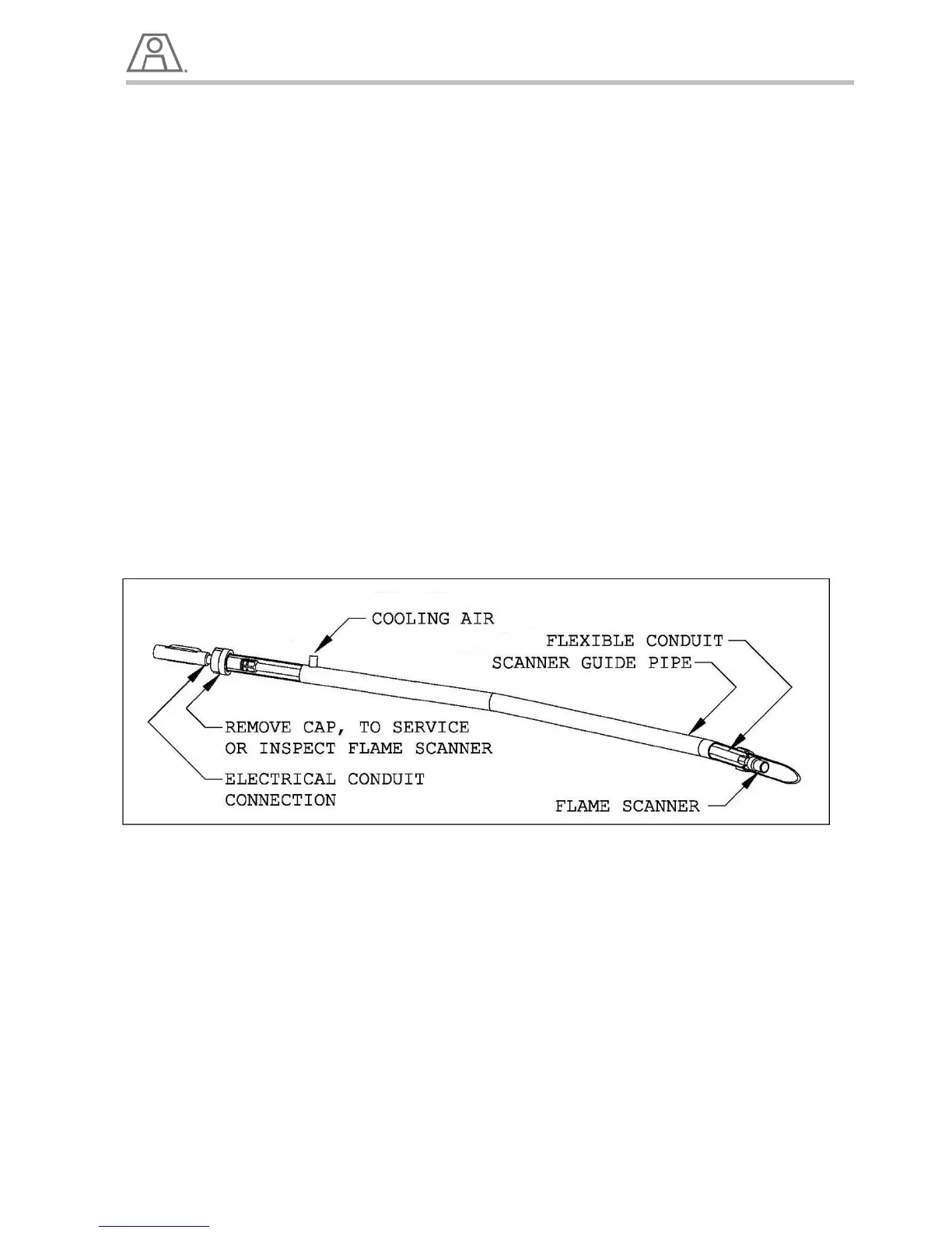
Flame Scanner
The PHOENIX TALON is supplied with a Flame Scanner that detects Ultra Violet (UV) in the flame. The
flame scanner is located in an air cooled guide tube near the front of the burner. It can be removed by
unthreading the 1 ¼” aluminum cap on the back of the burner and pulling the flexible conduit attached to
it out.
NOTE:
Be careful not to physically shock or overheat the Flame Detector as this can cause it to fail.
Illustration 12 – Flame Scanner
Pilot and UV Cooling Air
The Pilot and flame scanner require cooling air at a constant pressure from the plant compressed air
supply to prevent dust buildup in front of the scanner lens. Dust buildup on the scanner lens will degrade
accurate flame readings and may cause nuisance shutdowns.