PHOENIX Talon - Operation and Service Manual
7
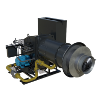
Receiving and Inspection
Upon receipt of the Burner:
1. Check each item on the bill of lading and/or invoice to determine that all the equipment that was
shipped has been received.
2. Carefully examine all of the equipment, assemblies and subassemblies to check if there has been
any damage in shipment.
3. If there are any damaged or missing parts, contact ASTEC Burner Systems Group for assistance.
(423-867-4210, or FAX 423-827-1560)
NOTE:
If the installation is delayed and the equipment is to be stored outside:
1. Provide adequate protection, as dictated by your climate and the period of exposure.
2. Special care should be given to all; motors, hydraulics, electrical parts, and bearings, to protect them
from rain, snow, or excessive moisture.
Burner Capacity
Table - 1 Burner Capacities
Notes: For Table-1
1. The maximum BTU/hour rating is based on 20% excess air.
2. The figures used in Table – 1 are based on: 60Hz AC, and Standard Cubic Feet per Hour (SCFH), at
70F air temperature, at sea level.
3. Correction factors must be applied for altitude or temperature variations. (See Altitude Correction
Chart.)
4. Viscosity of the oil delivered to the burner at 220
o
F must be 80 SSU (maximum) or lower.
5. The system exhaust fan must have enough capacity to provide a slight negative pressure (0.20” to
0.30" water column) at the burner breech plate. (This will exhaust the products of combustion, and
prevent “puffing” at the breeching plate.)
6. The air flow in the PHOENIX Talon can be monitored using the pressure tap on the side of the burner
blower housing. (The air pressure for a given flow is in the individual burner capacity tables.)
7. The values of differential pressure versus flow is listed in the individual burner capacity sheets.
8. The air required to atomize the fuel is provided by compressed air during oil firing. (See note-4)
9. The gas flow in the PHOENIX Talon can be measured using the orifice plate provided in the gas line.
PT-50 660,000 11,000 40 55,000 6.5 55,000,000
PT-75 1,000,000 16,667 60 83,000 10 83,000,000
PT-100 1,284,000 21,400 75 110,000 13 110,000,000
PT-125 1,600,000 26,667 100 137,000 16 138,000,000
PT-150 2,000,000 33,333 125 165,000 20 165,000,000