PHOENIX Talon - Operation and Service Manual
16
Burner Model PT-50 PT-75 PT-100 PT-125 PT-150
55,000
Cu Ft/Hr
82,500
Cu Ft/Hr
110,000
Cu Ft/Hr
137,500
Cu Ft/Hr
165,000
Cu Ft/Hr
4.3 PSI 5.3 PSI 4.5 PSI 7.6 PSI 7.2 PSI
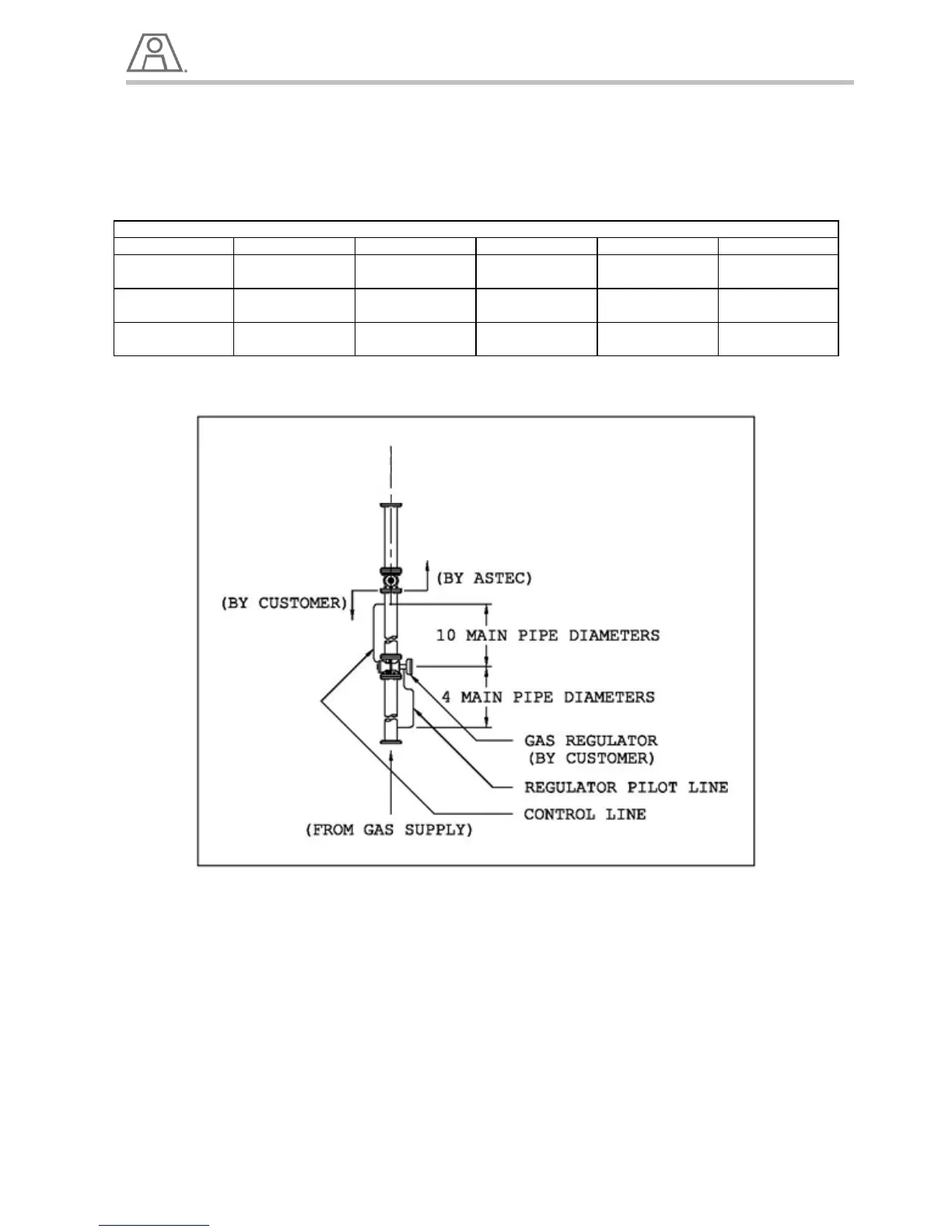
NATURAL GAS REGULATOR REQUIREMENTS
NOTE:
The low and high gas pressure switches should be set just above and below the safe operating range of
gas inlet pressures respectively. This should be individually determined on each installation. Typically this
would be 50% of the running pressure for the low gas pressure switch and 125% of the operating
pressure for the high gas pressure switch.
Table 5 - Natural Gas Regulators
Illustration 7 - Regulator Requirements
6. The gas valve is close coupled to its actuator, eliminating all linkages
7. See individual burner performance sheets for air and gas flows. (See Detailed Burner Performance
Sheets)
8. Use the utmost care in making any adjustment to prevent an unsafe condition.
WARNING!
The settings in Table 5 are for the initial set-up only.
Final settings will have to be adjusted for the particular operating conditions.
Be sure not to have more fuel flow than there is combustion air available to burn, or "puffing", and
a dangerously rich firing condition could occur.