PHOENIX Talon - Operation and Service Manual
19
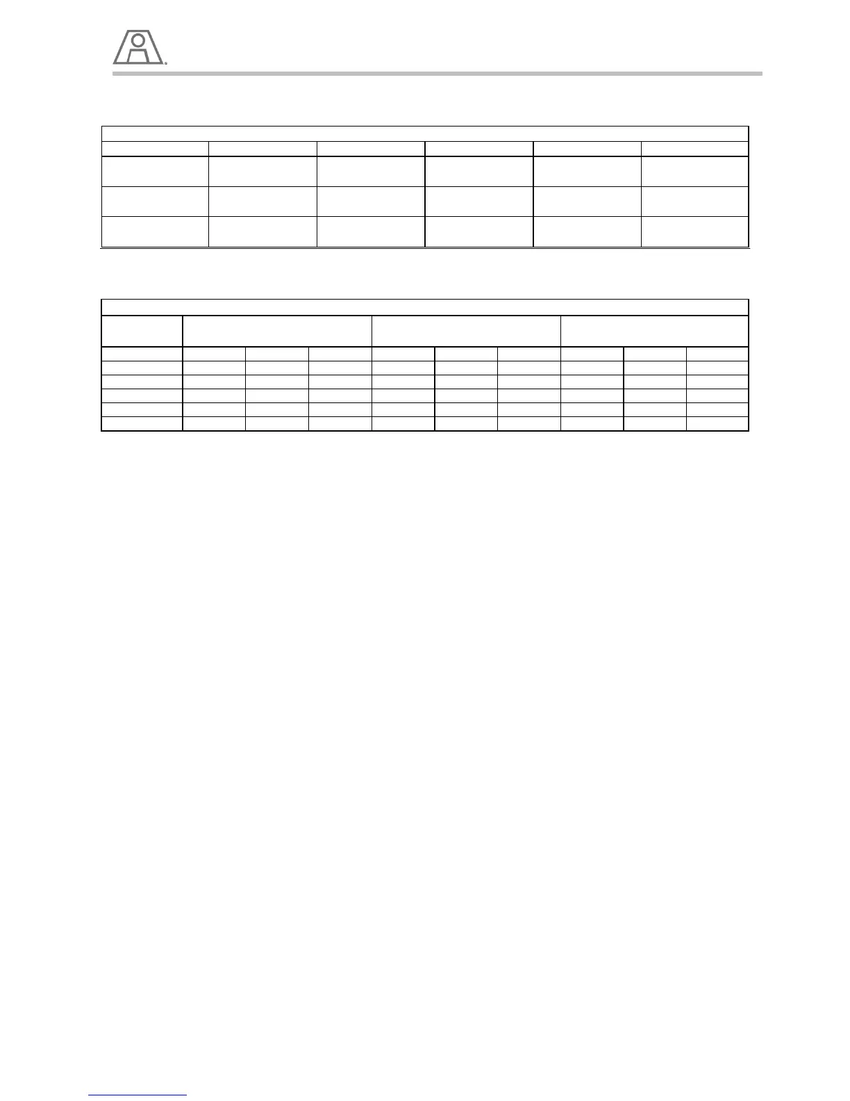
Burner Model PT-50 PT-75 PT-100 PT-125 PT-150
6.5 GPM 9 GPM 13 GPM 16 GPM 19 GPM
Typical Gas Inlet
Pressure
90 PSI 84 PSI 122 PSI 100 PSI 104 PSI
Burner Model 0' to 25' 25' to 49' 50' to 100' 0' to 25' 25' to 49' 50' to 100' 0' to 25' 25' to 49' 50' to 100'
PT-50 1" 1" 1" 1" 1" 1-1/4" 1-1/4" 1-1/4" 1-1/2"
1" 1" 1" 1" 1-1/4" 1-1/4" 1-1/4" 1-1/2" 2"
1" 1" 1-1/4" 1-1/4" 1-1/4" 1-1/4" 1-1/4" 1-1/2" 2"
1" 1-1/4" 1-1/4" 1-1/4" 1-1/4" 1-1/4" 1-1/4" 2" 2"
1" 1-1/4" 1-1/4" 1-1/4" 1-1/4" 1-1/2" 1-1/2" 2" 2"
Return Line In Feet,
Light Oil (Up to 100 SSU)
Return Line In Feet,
Heavy Oil (Over 100 SSU)
Table 6 – Oil Train Settings
Table 7 – Minimum Oil Line Size for various lengths
1. For recommended pipe sizes, see Table - 7.
2. Before attaching the fuel lines, purge the piping to remove scale, dirt, and other contaminates that
could clog and damage the fuel system.
3. Adjust the pressure control valve until the required oil pressure is achieved. (See the Individual
Burner Performance Data Sheets for the approximate settings.)
4. Depending on the system design, the final pump pressure will have to be adjusted to attain the
desired burner output.
5. The low oil pressure switch is factory set at 30 PSIG.
6. The low oil pressure switch should be set about 10 PSIG lower than the actual pressure required
WARNING!
Fuel leaked from the oil piping presents an extreme fire danger.
7. Leak test the piping before start-up, then check for leaks daily.
8. The manual low fire bypass oil control valve is used to set and maintain the low fire oil flow at the
burner. (See the Individual Burner Performance Data Sheets for the low fire oil setting.)
9. The burner oil flow (metering) control valve range is usually set from position 0 to Position 12.
10. The high fire oil flow can be set by varying the fuel pressure, or by changing the valve profile in the
control system. (See the Individual Burner Performance Data Sheets for proper fuel flows.)
11. Oil flow rates can be checked with the inline oil flow meter in the fuel control valve train.
12. Oil flow rates can be confirmed using the nozzle pressure and the burner performance data sheet.
WARNING!
The settings are for the initial set-up only.
Final settings will have to be adjusted for the particular operating conditions.
Be sure not to have more fuel flow than there is combustion air available to burn, or "puffing", and
a dangerously rich firing condition could occur.