5
e series saltwater chlorinator Installation Manual
4
e series saltwater chlorinator Installation Manual
Section 2. System Overview
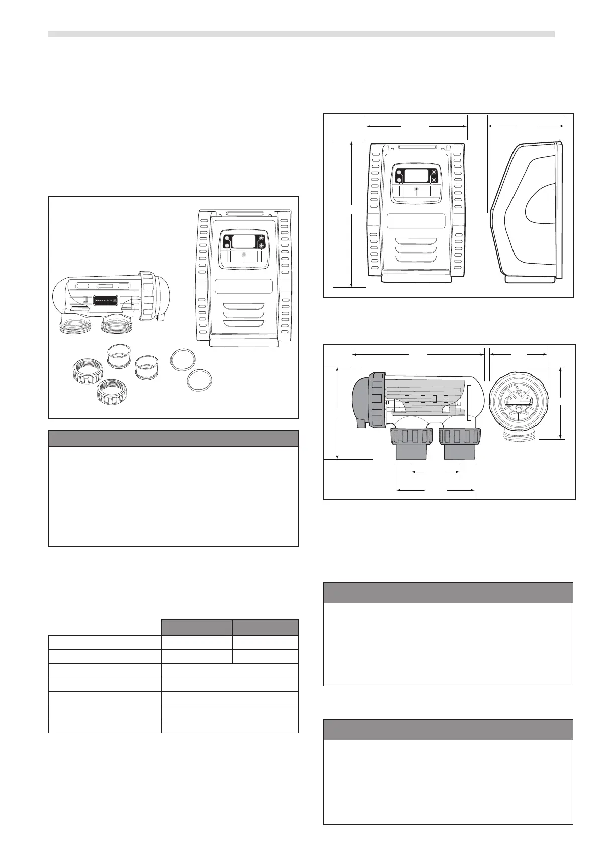
2.1 Contents
Before starting, check that you have the correct parts
as indicated in Table 1. If any parts are missing or
incorrect, please call your local distributor or technical
support at 1300 186 875 for assistance.
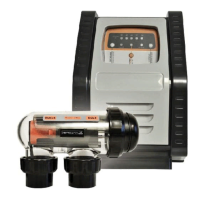
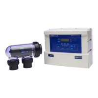
2.2 Salt Chlorinator System
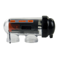
Outlet
Intlet
Direction of Flow
ENTER
MENU
UP
AUTO
DOWN
E25/E35 Saltwater Chlorinator
a. Controller
b. Wall Mount Bracket
c. Wall Mount Screws Ø7 mm (X2)
d. Wall Mount Anchor (X2)
e. Electrolytic Cell
f. Unions (X2)
g. 50mm Glue on Adapter (X2)
h. O-ring (X2)
Table 1. Salt Chlorinator System Contents
2.3 Specifications
2.3.1 Salt Chlorinator System
E 25 E 35
Nominal chlorine production 25 g/h 35 g/h
Nominal output amps 4.4 A 5.8 A
Required salt level 6000ppm
Power supply voltage 230 - 240 VAC
Protection index IP23
Flow through the cell Min. 80 Lpm
Operating water temperature 10°C - 40°C
Table 2. Salt Chlorinator System Specifications
2.4 Dimensions
2.4.1 Controller
ENTER
MENU
UP
AUTO
DOWN
22.54 cm
13.15 cm
32.3 cm
Figure 1. Controller Dimensions
2.4.2 Cell
32 cm
11.5 cm
21.5 cm
11 cm
21.5 cm
15.5 cm
Figure 2. Electrolytic Cell Dimensions
2.5 Materials and Tools
2.5.1 Controller
Tools Needed for Installation
• Power Drill
• 7 mm Drill Bit - Hammer Drill Bit
(only necessary to drill into brick or concrete)
• Pencil or Marking Pen
• Pozidriv Screwdriver
2.5.2 Cell
Tools Needed for Installation
• PVC Cutter
• PVC Cement
• Pencil or Marking Pen
• Check Valve
• 50 mm PVC Pipe (40mm optional)