Features and benefits of your SPLASHER
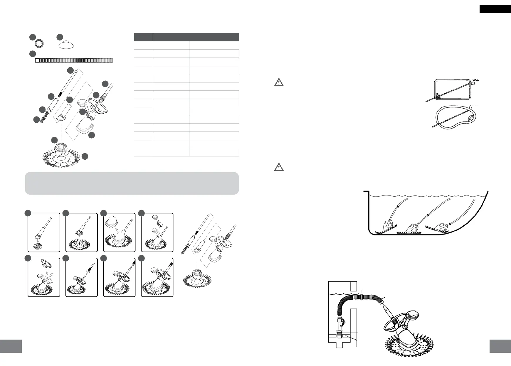
SPLASHER Components and Spare Parts diagram
1. Fit the exi foot to the cleaner main body, ensuring the main body lower ange is properly secured into
the exi foot locating groove (picture 1)
2. Place the inner top of the ned disc onto the exi foot pad ange and peel over until the disc is secure
between the ange and top of the exi foot pad. The ns of the disc and the word “TOP” should face
the cleaner main body. (picture 2)
3. Place the cleaner shroud (Silver) over the inner tube and slide down onto the main body. The main
body has a location key that needs to align with a groove within the shroud. This ensures the shroud
is installed correctly. (picture 3)
4. Place the cleaner oat assembly over the inner tube and on top of the shroud. This also needs to
bealigned to the main body location key. (picture 4)
5. Slide the cleaner deector wheel over the inner tube until located on top of the oat assembly. The
deector wheel does not align with the locating key on the main body and is able to spin freely on the
top section of the main body. (picture 5) NOTE: The deector ring can be removed and replaced with
a SPLASHER cone to enhance performance, depending on pool shape
6. Slide the outer tube assembly down the inner tube and screw the nut into place as this will secure the
deector wheel. (picture 6)
7. Connect sufficient lengths of cleaner hose to cover the distance from the pool skimmer box or weir to
the furthest point of your pool, plus one length. (picture 7)
8. Congratulations your SPLASHER pool cleaner is ready for installation into your pool!
SPLASHER Assembly
Hose assembly:
The pump must be on when you check the hose length. The hose
contracts when the pump is operating and will be longer when
the pump is off.
While the cleaner is operating:
1. Position cleaner at the furthest point of the pool from where
it’s attached. (Use a pool pole and brush to easily position the
cleaner in the pool.)
2. The hose should be long enough to reach the end of the pool,
plus one hose section. (The hoses are universal hoses and t
directly into each other).
3. If there is excess hose, be sure to remove the sections from the center portion of hose. This
avoids disturbing the hose weight placement.
4. Save extra hose sections for use as needed for replacement. Always keep extra hoses stored
in a straight position.
Note: Turn pool pump off when adding or removing hose sections.
Attaching hose weights
To determine correct hose balance,
turn the pump off and note the cleaner’s
position in the pool. Correct Hose Balance:
Cleaner seal sits at on the pool oor and
the drive tube makes 45° angle with the
pool oor.
For maximum cleaning coverage, the hose
does not pull up or down on the unit. Adjust
hose weight one inch at a time, as needed,
to achieve proper hose balance.
In pools with both shallow and deep areas,
adjust hose weights rst in the deep area
and then in the shallow area.
Installation
Weir installation
No Code Description
1 630-9080 Hose Weight
2 570-0007 Easy Out Jogger
3 630-6210 1m Unit Hose
4 630-9068 Diaphragm Round
5 630-9069 Inlet Plate
6 630-9079 Cartridge
7 630-9067 Inner Tube
8 630-9083 Main Body
9 630-9073 Shroud
10 630-9078 Float Set
11 630-9072 Deector Wheel
12 630-9085 Outer Tube
13 630-9070 Flexi Foot
14 630-9071 Finned Disc
1 2
3
4
5
6
7
8
9
10
11
12
13
14
EASY OUT JOGGER CONE:
Place Easy Out Jogger between 2nd and 3rd hose length, small side facing the weir and the
bigger side facing the cleaner. The Easy Out Jogger Cone will sit/lie on top of the water
1
5
2
6
3
7
4
8
Include universal adaptor.
Hose Weight (1-2 hose lengths from cleaner)
Hose Lengths
Splasher
Universal Adaptor
Skimmer Plate
ENGLISH
Incorrect Correct Incorrect
0706
 Loading...